
Embedded optical pressure measurement method for shelter position of hypersonic wind tunnel model

A hypersonic, measurement method technology, used in measurement devices, machine/structural component testing, aerodynamic tests, etc., can solve the problem that the light source and the camera optical path cannot be directly reached, and maintain the technical parameters unchanged and high reliability. The effect of low uniformity and light intensity uniformity

Active Publication Date: 2020-01-17
中国空气动力研究与发展中心超高速空气动力研究所
View PDF8 Cites 5 Cited by
  • Summary
  • Abstract
  • Description
  • Claims
  • Application Information

AI Technical Summary

Problems solved by technology

Similarly, similar to the parallel two-stage aircraft, due to the occlusion of the main body of the aircraft, the light path of the light source and the camera cannot directly reach the inside of the air inlet, and the pressure measurement inside the air inlet cannot be measured from the self-contained air inlet. Aircraft model external implementation

Method used


Image

  • Embedded optical pressure measurement method for shelter position of hypersonic wind tunnel model
  • Embedded optical pressure measurement method for shelter position of hypersonic wind tunnel model

Examples


Embodiment 1

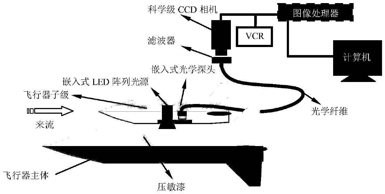
[0026] Such as figure 1 As shown, the device used in the embedded optical pressure measurement method of the hypersonic wind tunnel model occlusion position of the present invention includes an embedded LED array light source, an embedded optical probe, a scientific grade CCD camera, a filter, an optical fiber, and an image storage and processing system , the image storage processing system comprises VCR, image processor and computer, and described measurement method comprises the following steps:

[0027] a. Process a set of parallel two-level wind tunnel test models, the first-level model is the main body of the aircraft, and the second-level model is the sub-level of the aircraft that is fixedly installed above the main body of the aircraft with a gap between it and the main body of the aircraft;

[0028] b. Process a groove on the lower surface of the second-level model, install the embedded LED array light source and embedded optical probe side by side in the groove, the ...

Embodiment 2

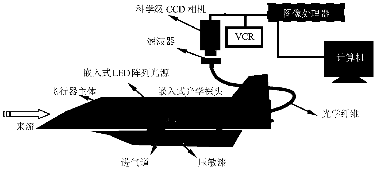
[0038] Such as figure 2 As shown, the implementation of this embodiment is basically the same as that of Embodiment 1, the main difference is that the parallel two-stage wind tunnel test model in the step a is replaced by an independent aircraft model with an air intake, and the independent air intake The first-level model of the airway aircraft model is the main body of the aircraft, and the second-level model is the air inlet.

[0039] The optical fiber in Embodiment 1 and Embodiment 2 can be replaced by a light guide arm.


PUM


Abstract

The invention discloses an embedded optical pressure measurement method for the shelter position of a hypersonic wind tunnel model. The measurement method comprises the following steps: firstly, processing a parallel two-stage wind tunnel test model, arranging an embedded LED array light source and an embedded optical probe side by side in a groove in the lower surface of a second stage model, covering the surface of the groove with an optical glass window, connecting the embedded optical probe with an external scientific CCD camera and an image storage processing system, coating a measurementposition, corresponding to the optical glass window, on the upper surface of a first stage model with pressure sensitive paint, processing a pressure measurement hole, and connecting the pressure measurement hole with a wind tunnel pressure measurement system; secondly, acquiring a wind-on image, a wind-off image and a wind-dark at the measurement position in a wind tunnel test, and then acquiring a gray ratio image through image processing; and finally, drawing a calibration curve through the gray ratio image and the pressure value of the pressure measurement hole, and fitting a calibrationformula to obtain a pressure distribution map. The measurement method is simple and efficient, and the problem of large area pressure measurement of the model under a shelter situation is solved.

Description

technical field [0001] The invention belongs to the technical field of hypersonic wind tunnel tests, and in particular relates to an embedded optical pressure measurement method for the occlusion position of a hypersonic wind tunnel model. Background technique [0002] During the high-speed separation process of the parallel two-stage aircraft, there is a very complex flow field structure between the first stage and the second stage, which is the main measurement area of ​​the hypersonic wind tunnel test. The parallel two-stage aircraft model is a test where there is a model shielding position Model. Although conventional pressure-sensitive paint can obtain large-area pressure continuous measurement data, for test models with model occlusion locations, the light source or camera cannot reach the surface of the measurement location due to mutual occlusion between the first-level model, the second-level model, or the interior of the model. The conventional method is to simpli...

Claims


Application Information

Patent Timeline
Patent Type & Authority Applications(China)
IPC IPC(8): G01M9/06
CPCG01M9/06
Inventor 解福田林敬周张庆虎陈念年钟俊许晓斌陈磊赵健陈久芬凌岗
Owner 中国空气动力研究与发展中心超高速空气动力研究所
Learn More