Method for detecting sonic time and tracking phase wave band of concrete pile shaft by ultrasonic transmission method

A technology of concrete piles and wave bands, which is applied in the direction of analyzing solids using sound waves/ultrasonic waves/infrasonic waves, which can solve the problems of difficult identification of data and large errors

Active Publication Date: 2013-12-18
北京市康科瑞工程检测技术有限责任公司
View PDF1 Cites 0 Cited by
  • Summary
  • Abstract
  • Description
  • Claims
  • Application Information

AI Technical Summary

Problems solved by technology
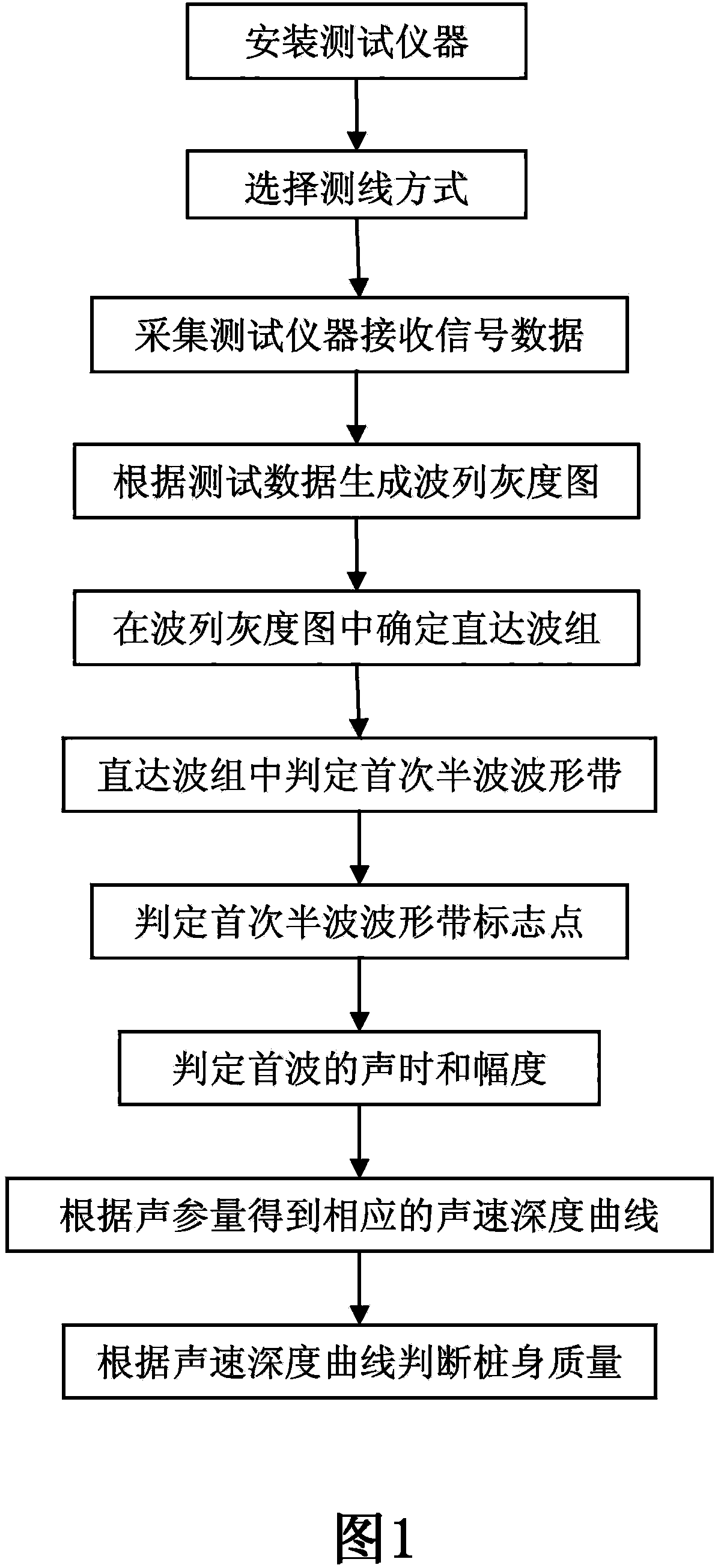
[0016] The purpose of the present invention is to provide a method for tracking the same-phase waveform band during acoustic detection of concrete piles through the sound penetration method, to solve the technical problem that the error of the traditional measurement method is relatively large and the detection result can only be obtained after the completion of the data processing in the later stage, and to solve the problem of receiving Wave signal amplitude changes are the basic basis for the problem that the data is not easy to identify, and it also solves the technical problems that the data obtained during real-time misjudgment must be corrected one by one, and the error caused by direct interpretation of the waveform diagram is relatively large

Method used


Image

  • Method for detecting sonic time and tracking phase wave band of concrete pile shaft by ultrasonic transmission method
  • Method for detecting sonic time and tracking phase wave band of concrete pile shaft by ultrasonic transmission method
  • Method for detecting sonic time and tracking phase wave band of concrete pile shaft by ultrasonic transmission method

Examples


Embodiment 1

[0092] Embodiment 1: An ultrasonic instrument for a pile is detected using an oblique measurement method:

[0093] see Figure 11 Shown is the sound velocity and amplitude curves automatically interpreted by the traditional method in real time. Due to various judgment errors, the sound velocity and amplitude curves automatically interpreted in real time jump out of order, and the quality of the pile body cannot be judged. see Figure 12 Shown is the wave train grayscale image of Embodiment 1, the application of the present invention can clearly identify the direct wave group 9 in the figure, and obtain the first half-wave wave band 2, see Figure 13As shown, and the corresponding sound velocity curve 12 is obtained by judging the sound of the first wave. In this embodiment, according to the sound velocity curve 12, the quality of the pile body is basically stable and consistent, and it is determined as a first-class pile.

Embodiment 2

[0094] Embodiment 2: An ultrasonic instrument for a pile is detected using an oblique measurement method:

[0095] see Figure 14 Shown is the sound velocity and amplitude curves automatically interpreted by the traditional method in real time. From the figure, it can be seen that the sound velocity and amplitude curves of the entire pile body jump out of order, and the quality of the pile body cannot be judged. see Figure 15 Shown is the wave train grayscale image of embodiment two, and the application of the present invention can clearly identify the direct wave group 9 in the figure, and obtain the first half-wave wave band 2, see Figure 16 As shown, and the corresponding sound velocity curve 12 is obtained by judging the sound of the first wave. In this embodiment, according to the sound velocity curve 12, the quality of the pile body is basically stable and consistent, and it is determined as a first-class pile.

Embodiment 3

[0096] Embodiment 3: An ultrasonic instrument for a pile is detected using an oblique measurement method:

[0097] see Figure 17 Shown is the sound velocity and amplitude curves automatically interpreted by the traditional method in real time, see Figure 18 Shown is the wave train grayscale image of Example 3. The grayscale image of the half-wave waveform is clearly disconnected for the first time between 4.0m and 5.0m, indicating that there are obvious mud inclusion defects in this section.


PUM


Abstract

The invention discloses a method for detecting sonic time and tracking phase wave bands of a concrete pile shaft by ultrasonic transmission method, comprising the following steps: arranging testing points at regular intervals in depth direction of the pile shaft, determining a test mode, collecting received waveform samples and sonic parameter data, generating a wave train grey-scale map according to the collection of the waveform grey-scale maps of testing points, determining a first half-wave band in the wave train grey-scale map, determining a first half-wave band mark point in the range of the first half-wave band, and then determining the sonic time and amplitude of the first wave, calculating a corresponding acoustic velocity depth curve according to the sonic time value, and determining the quality of the pile shaft according to the acoustic velocity depth curve. According to the invention, the defects of great errors and detection results obtained only after completing data post-processing in traditional measuring methods are solved, the problem of uneasy identification of data caused by using received wave signal amplitude change as a fundamental basis is solved, and the technical problems that the data obtained in real-time misjudgment must be corrected one by one and great errors are caused by directly identifying waveform graphs are solved.

Description

technical field [0001] The invention relates to a method for detecting the quality of concrete piles, in particular to a method for detecting the quality of concrete pouring piles using an ultrasonic transmission method. Background technique [0002] Ultrasonic transmission method is an extremely widely used technology to detect the quality of concrete pouring piles. Its basic principle is to judge the integrity of pile concrete by using the change of acoustic parameters. The acoustic parameters are mainly the sound time and amplitude of the first wave. [0003] The transmitting transducer emits a group of oscillating waveforms, which are received by the receiving transducer after propagating through the concrete of the pile body. The wave group propagating along the straight line between the transmitting transducer and the receiving transducer is called the direct wave group. The wave groups propagated by other paths are non-direct wave groups. Generally, the non-direct wav...

Claims


Application Information

Patent Timeline
Patent Type & Authority Patents(China)
IPC IPC(8): G01N29/04G01N29/07
Inventor 濮存亭卫红郭启亮阚月鹏邓龙贺志云李屹阴洪恩穆铁军
Owner 北京市康科瑞工程检测技术有限责任公司
Why Eureka
Try Eureka