

A controller local area network bus communication control method, device and system
A local area network bus and controller technology, applied in transmission systems, bus networks, digital transmission systems, etc., can solve problems such as wrong bus bandwidth and waste of network resources
- Summary
- Abstract
- Description
- Claims
- Application Information
AI Technical Summary
Problems solved by technology
Method used
Image


Examples
Embodiment 1
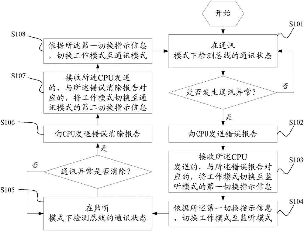
[0050] The flow chart of a controller LAN bus communication control method provided in Embodiment 1 of the present application is as follows: figure 1 shown, including:
[0051] Step S101: Detect the communication state of the bus in the communication mode, and judge whether the communication of the bus is abnormal, if so, execute step S102, otherwise, continue to execute step S101;
[0052] Step S102: sending an error report to the CPU;
[0053] In the controller local area network, under normal circumstances, the working mode of the CAN controller is in the communication mode. In this embodiment, the CAN controller detects the communication state of the bus in the communication mode, and judges whether the communication abnormality occurs in the bus. When the communication is abnormal, send an error report to the CPU; otherwise, continue to detect whether there is a communication abnormality on the bus.
[0054] Step S103: receiving the first switching instruction informat...
Embodiment 2
[0068] The flow chart of a controller LAN bus communication control method provided in Embodiment 2 of the present application is as follows: figure 2 shown, including:
[0069] Step S201: receiving the error report sent by the CAN controller;
[0070] Step S202: sending the first switching indication information corresponding to the error report, instructing the CAN controller to switch the working mode to the listening mode;
[0071] After receiving the error report sent by the CAN controller, the CPU sends the first switching instruction information to the CAN controller, instructing the CAN controller to switch the working mode from the communication mode to the monitoring mode;
[0072] Step S203: receiving the error elimination report sent by the CAN controller;
[0073] Step S204: Sending second switching instruction information corresponding to the error elimination report, instructing the CAN controller to switch the working mode to the communication mode.
[0074...
Embodiment 3
[0077] A schematic structural diagram of a CAN controller provided in Embodiment 3 of the present application is as follows image 3 shown, including:
[0078] The first detecting module 301, the first receiving module 302, the second detecting module 303, the second receiving module 304 and the switching module 305;
[0079] The first detection module 301 is used to detect the communication status of the bus in the communication mode, and when detecting abnormal communication, send an error report to the CPU;
[0080] The first receiving module 302 is configured to receive first switching instruction information sent by the CPU and corresponding to the error report for switching the working mode to the monitoring mode;
[0081] The second detection module 303 is used to detect whether the communication abnormality is eliminated in the monitoring mode, and send an error elimination report to the CPU when the communication abnormality is eliminated;
[0082] The second receiv...
PUM
 Abstract
Description
Claims
Application Information