

Imaging device
A technology of camera device and camera element, which is applied in the direction of image communication, TV, color TV parts, etc. It can solve the problems of shortening the release time lag and increasing the number of continuous shots, etc., and achieve the effect of increasing the number of continuous shots.
- Summary
- Abstract
- Description
- Claims
- Application Information
AI Technical Summary
Problems solved by technology
Method used
Image

Examples
Embodiment approach 1
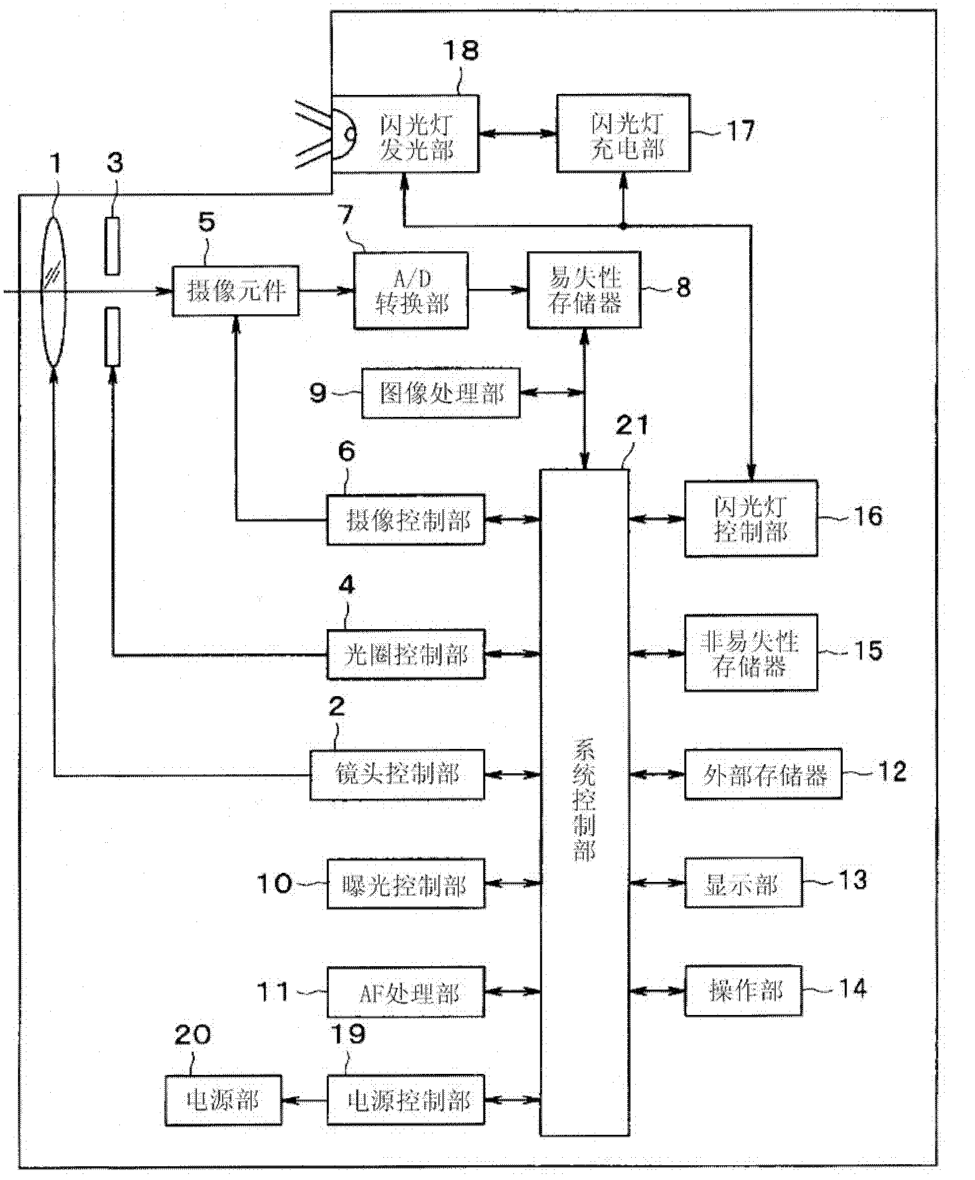
[0032] Figure 1 to Figure 12 Embodiment 1 of the present invention is shown, figure 1 It is a block diagram showing the configuration of the imaging device.
[0033] Such as figure 1 As shown, the imaging device has: a lens 1 and a lens control unit 2 as a lens unit; an aperture 3 and an aperture control unit 4 as an aperture unit; an imaging element 5 and an imaging control unit 6 as an imaging unit; an A / D conversion unit 7. Volatile memory 8; Image processing unit 9; Exposure control unit 10; AF processing unit 11; Display unit 13; Operation unit 14; Non-volatile memory 15; 17 and flash light emitting unit 18; power control unit 19; power supply unit 20 and system control unit 21. In addition, in figure 1 Although the external memory 12 is also described in the figure, since the external memory 12 is configured as a memory card or the like detachable from the imaging device, it does not need to be a unique structure in the imaging device.
[0034] The lens 1 images...
Embodiment approach 2
[0113] Figure 13 with Figure 14 Embodiment 2 of the present invention is shown, Figure 13 It is a timing chart showing AF processing based on an image signal obtained from the imaging element 5 while a still image is being divided and read in the imaging device.
[0114] In this second embodiment, the same reference numerals are assigned to the same parts as those in the first embodiment described above, and description thereof will be omitted, and only differences will be mainly described.
[0115] In the above Embodiment 1 Figure 11 In the processing of , the exposure and readout of the image for photometry are performed between the divided readout of the still image, but in this Figure 13 In the processing of , exposure and readout of an image for high-speed video AF are performed instead of exposure and readout of an image for photometry. In addition, in this embodiment, an example is shown in which divided reading of a still image is performed four times.
[011...
Embodiment approach 3
[0149] Figure 15 with Figure 16 Embodiment 3 of the present invention is shown, Figure 15 It is a timing chart showing the process of performing pre-lighting and determining the flash light emission amount for main light emission based on the image signal obtained from the image pickup device 5 while dividing and reading a still image in the imaging device.
[0150] In this third embodiment, the same reference numerals are assigned to the same parts as those in the above-mentioned first and second embodiments, and description thereof will be omitted, and only differences will be mainly described.
[0151] In the above Embodiment 1 Figure 11 In the processing of , the exposure and readout of the image for photometry are performed between the divided readout of the still image, and in the second embodiment described above, Figure 13 In the processing of , the exposure and readout of the image for high-speed video AF are performed between the divided readout of the still ...
PUM
 Abstract
Description
Claims
Application Information