
Round cutting insert with anti-rotation feature

A cutting insert, anti-rotation technology, applied in the direction of milling cutting inserts, special-shaped round tools, turning equipment, etc., can solve problems such as cracking or breaking, insert damage, endangering the cutting quality of workpieces, etc.

Active Publication Date: 2012-07-18
KENNAMETAL INC
View PDF6 Cites 9 Cited by
  • Summary
  • Abstract
  • Description
  • Claims
  • Application Information

AI Technical Summary

Problems solved by technology

If the clamping screw becomes loose enough, it can vibrate violently within the surrounding pocket enough to become cracked or shattered, not only ruining the insert but also compromising the quality of the cut on the workpiece

Method used


Image

  • Round cutting insert with anti-rotation feature
  • Round cutting insert with anti-rotation feature
  • Round cutting insert with anti-rotation feature

Examples


Embodiment Construction

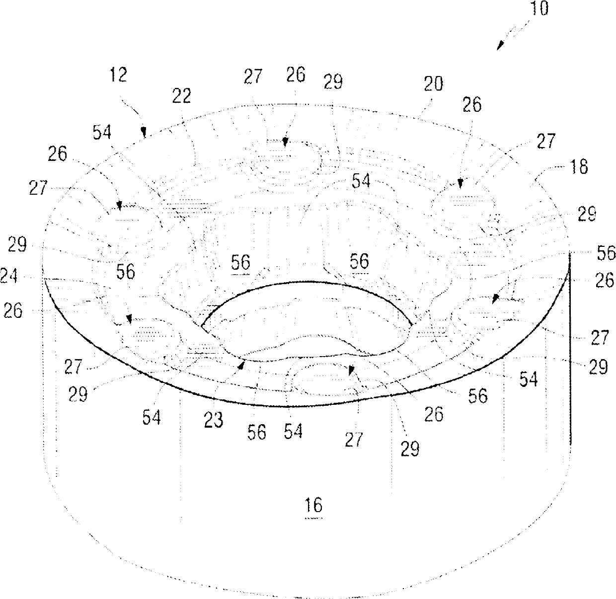
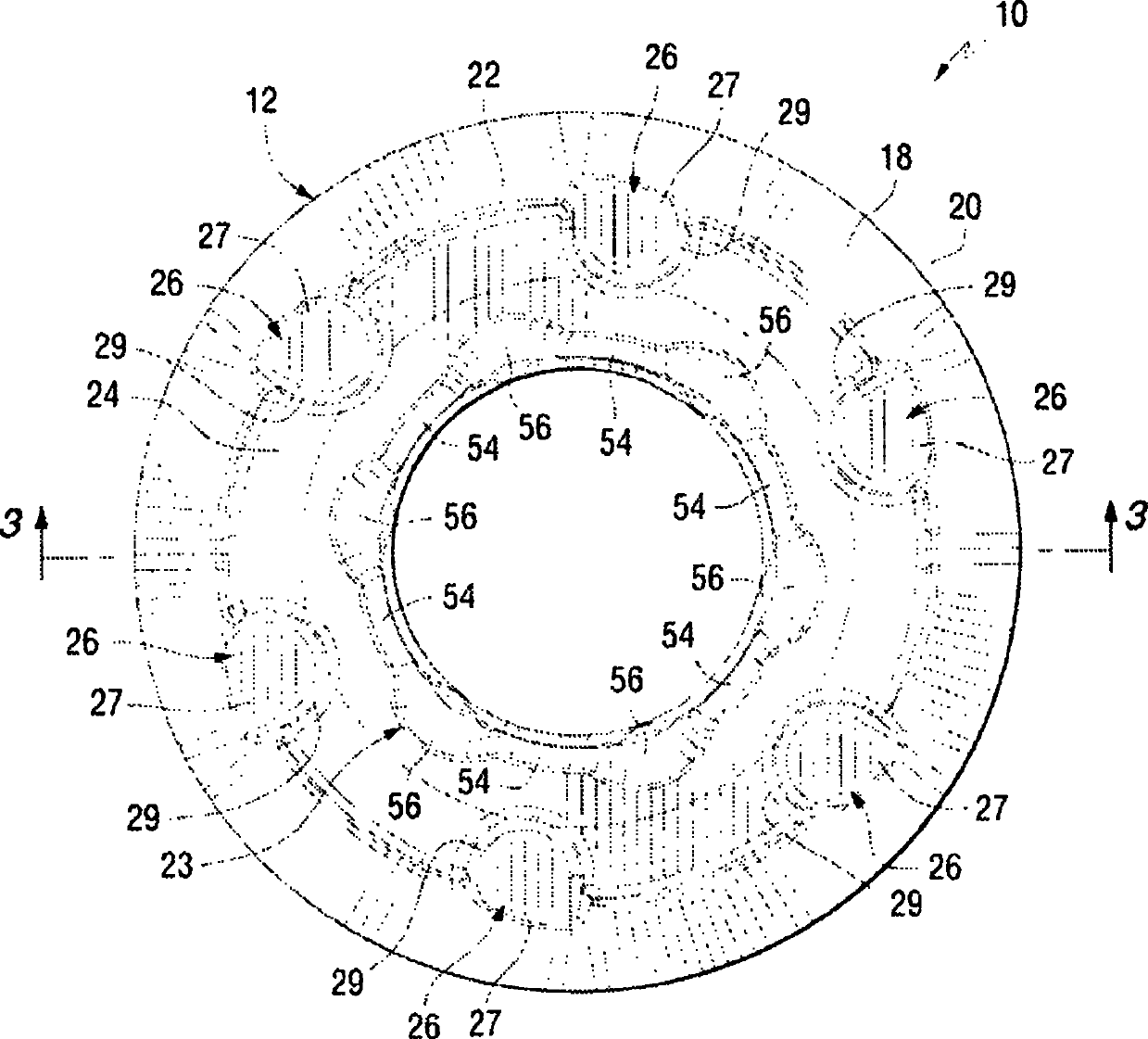
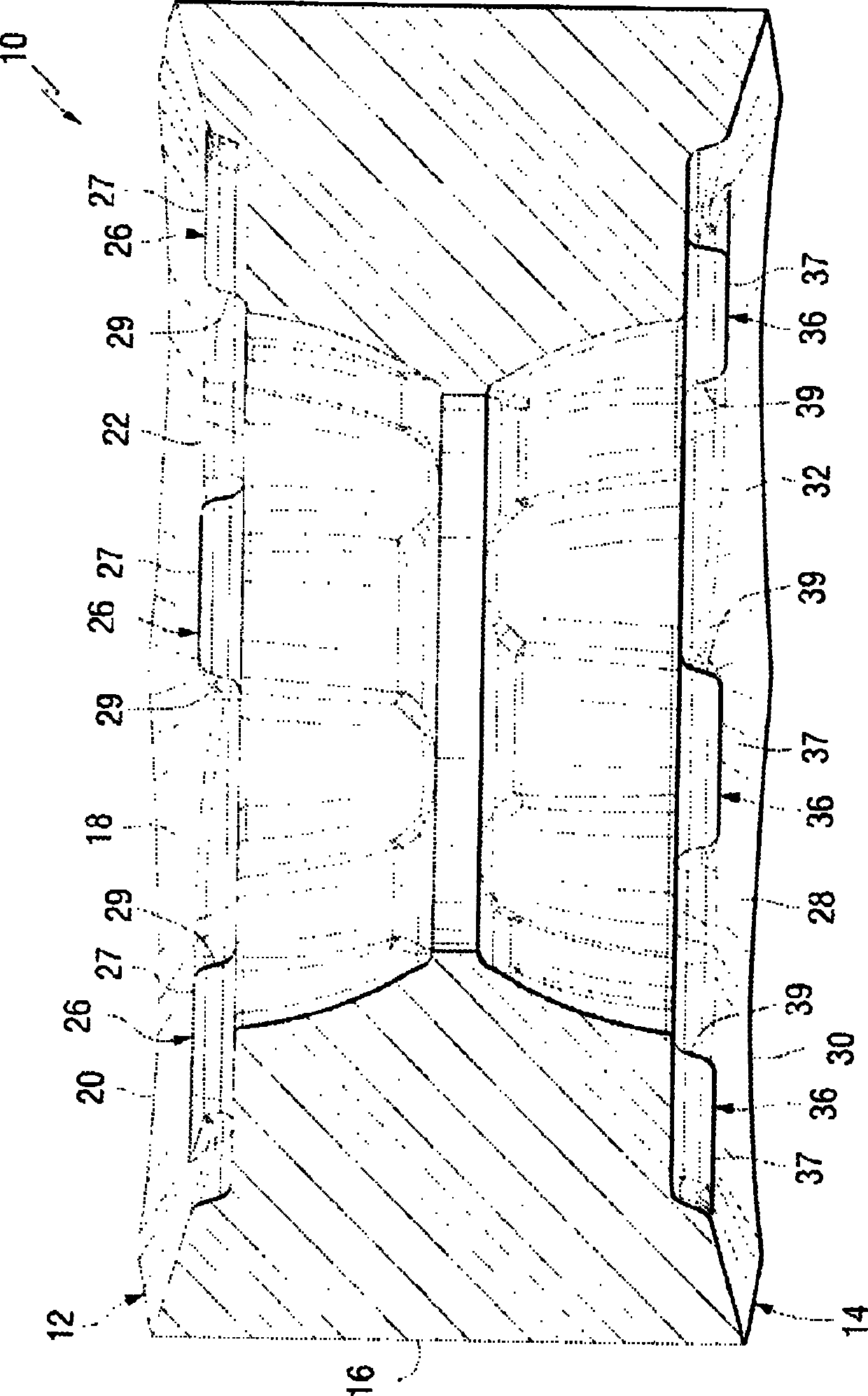
[0018] Referring to the figures, a cutting insert 10 is shown in accordance with one aspect of the present invention. The cutting insert 10 includes a first or top portion 12 (see generally figure 1 , figure 2 , image 3 and Figure 5 ) and a second or bottom portion 14 (see generally image 3 , Figure 4 and Figure 5 ) and a generally annular side portion 16 extending between the first portion 12 and the second portion 14. Thus, it should be appreciated that the cutting insert 10 is a generally circular cutting insert for positioning in a tool body for performing cutting operations on a workpiece (not shown).

[0019] like figure 1 and figure 2 As shown, the cutting insert 10 includes a first outer surface 18 that terminates in a first cutting edge 20 in a generally outward direction and terminates in a first cutting edge 20 in a generally inward direction. an inner edge 22 . In one aspect, the first outer surface 18 slopes from the first cutting edge 20 towards ...


PUM


Abstract

A round cutting insert (10) with an anti-rotation feature. The round cutting insert (10) includes a plurality of projections (26) formed on a first surface (12) and another plurality of projections (36) formed on an opposing surface (14). The round cutting (10) insert is reversible and indexable. The round cutting insert (10) is removably received in an insert receiving pocket (42) in a tool body (40) wherein the insert receiving pocket (42) includes a plurality of dimples (48) for receiving one of the plurality of first projections (26) or the plurality of second projections (36). This arrangement prevents rotation of the round cutting insert (10) while mounted in the insert receiving pocket (42).

Description

technical field [0001] The present invention relates generally to cutting inserts, and more particularly to circular cutting inserts having anti-rotation features for preventing rotation of the circular cutting insert mounted on a cutting tool body. Background technique [0002] A plurality of inserts used in cutters, such as milling cutters for example, are mounted in complementary shaped pockets spaced around the periphery of the cutter body. The inserts are typically secured in their corresponding pockets by clamping screws inserted through holes provided in the center of the insert. During cutting operations, such inserts are often subjected not only to compressive and vibratory forces, but also to a certain amount of torque caused by the angle between the cutting edges of these inserts and the workpiece. For cutting inserts having a non-circular shape, this is made possible by the interference fit between the angled side walls of such inserts and the complementary shap...

Claims


Application Information

Patent Timeline
Patent Type & Authority Applications(China)
IPC IPC(8): B23C5/20B23C5/22B23B27/16
CPCB23C5/2213B23C2200/168B23C2200/081B23C2200/045B23C2200/161B23C2210/168Y10T407/2268Y10T407/235Y10T407/24Y10T407/1936Y10T407/1934Y10T407/23Y10T407/20Y10T407/1924B23B27/16B23C5/20B23C5/22
Inventor L·R·莫里森K·R·米拉瓦雷姆尼基莱什T·J·朗J·F·科瓦克S·马里
Owner KENNAMETAL INC
Learn More