Gear machining machine

A technology for processing machinery and gears, applied in the direction of metal processing machinery parts, mechanical equipment, metal processing equipment, etc., to achieve the effect of improving rigidity and realizing processing accuracy

Inactive Publication Date: 2012-07-18
MITSUBISHI HEAVY IND LTD
View PDF6 Cites 6 Cited by
  • Summary
  • Abstract
  • Description
  • Claims
  • Application Information

AI Technical Summary

Problems solved by technology

Therefore, when the structure of the above-mentioned conventional cutting head is adopted in a milling

Method used


Image

  • Gear machining machine
  • Gear machining machine
  • Gear machining machine

Examples


Example Embodiment

[0033] Hereinafter, the gear processing machine of the present invention will be described in detail with reference to the drawings.

[0034] [Example]

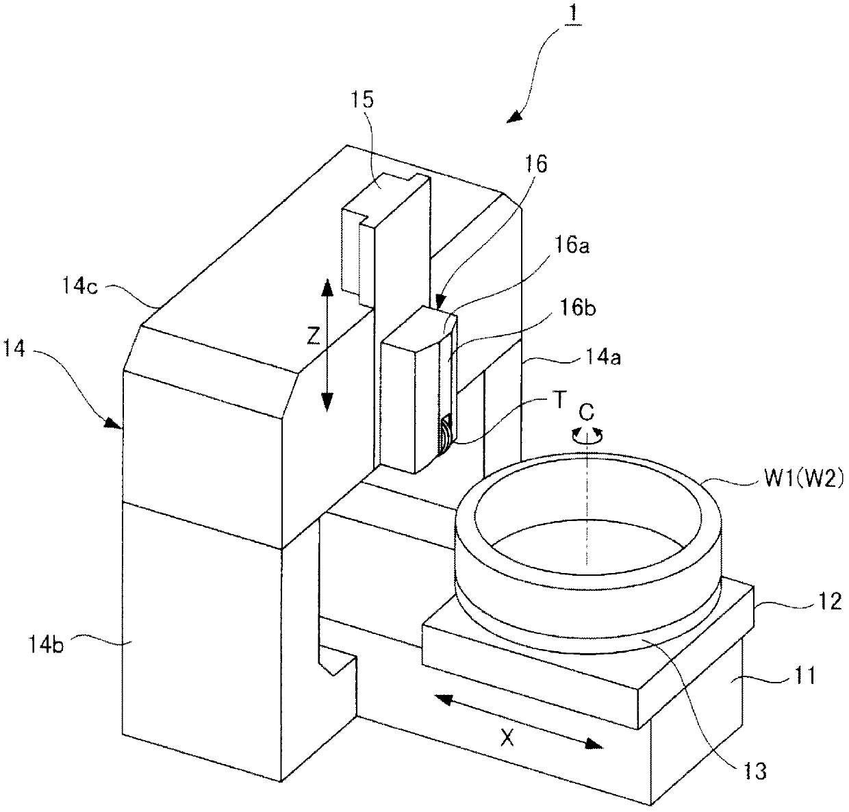
[0035] Such as figure 1 As shown, a gate-shaped gear processing machine 1 is provided with a machine tool 11, and a moving base 12 is supported on the machine tool 11 in a manner capable of moving along the horizontal X-axis direction. The circular rotating table 13 is supported on the upper part of the moving base 12 so as to be rotatable about the vertical workpiece rotation axis C. The upper surface of the rotating table 13 is selectively mounted with an external gear (outside the machine to be processed). Gear) W1 or internal gear (processed internal gear) W2.

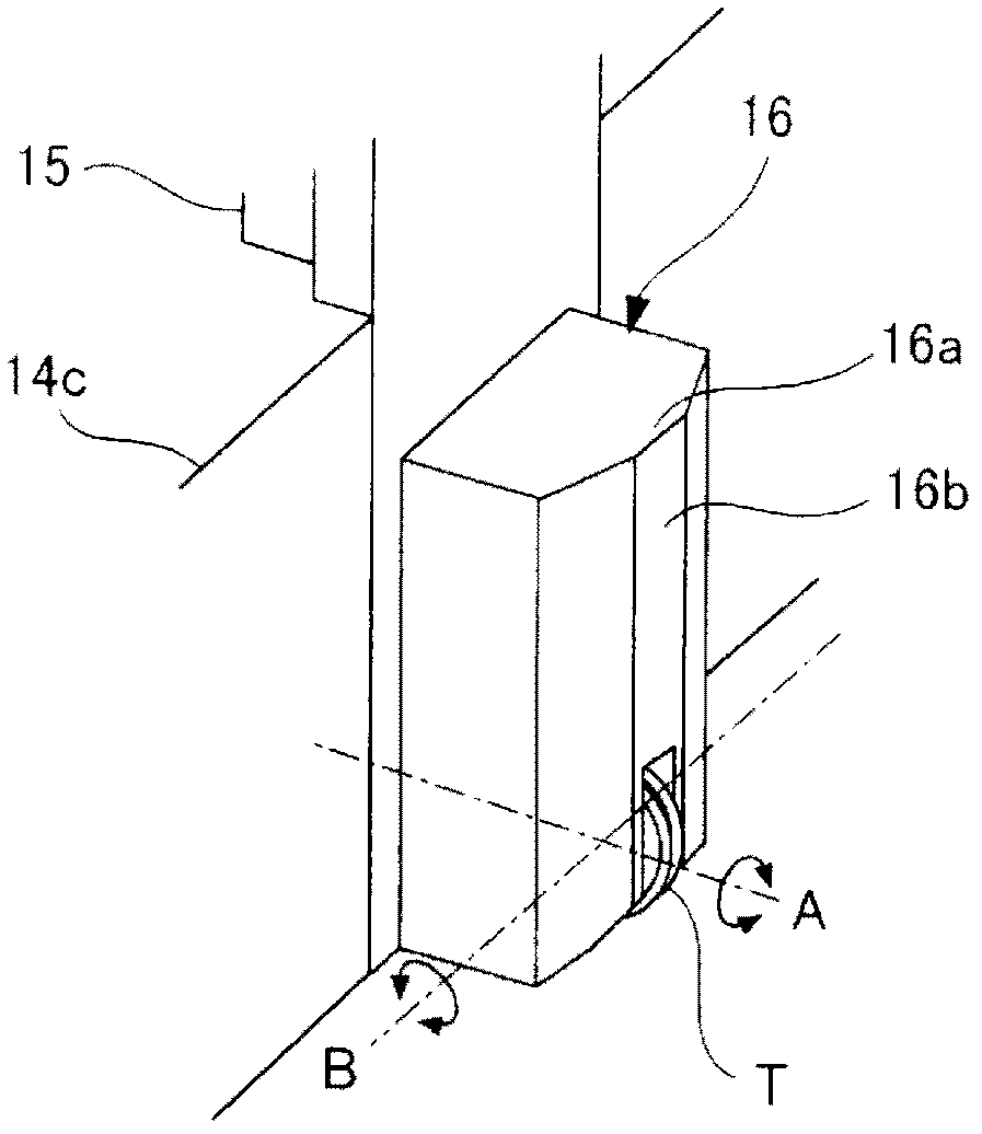
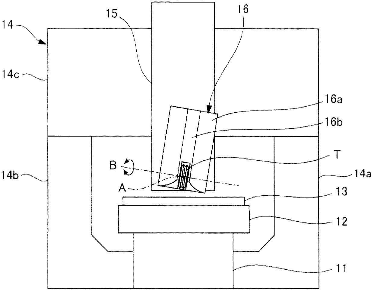
[0036] In addition, a gate-shaped column 14 is provided on the rear end side of the machine tool 11. The portal column 14 includes a pair of left and right column portions 14a, 14b erected on the left and right sides of the machine tool 11; and a bridge portion (suppor...


PUM


Abstract

Provided is a gear machining machine which has a cutter head with improved rigidity, and contributes to improving machining accuracy and making quality uniform when either an external gear or an internal gear has been machined. For this purpose, the gear machining machine is equipped with a movement base (12) that is movably supported and rotatably supports a rotation table (13) on which an external gear (W1) or an internal gear (W2) is mounted; a bridge section (14c) of a gate-shaped column (14) provided at a location above the movement base (12); a saddle (15) which is supported by the bridge section (14c) in a vertically movable manner; and a cutter head (16) which is provided on the front surface of the saddle (15), and the lower end of which rotatably supports a tool (T). A protrusion (16a) which projects forward is provided on the front surface of the cutter head (16). The tool (T) is disposed in such way that the front thereof protrudes further forward of an end surface (16b) which is the most forward projecting portion of the protrusion (16a).

Description

Technical field [0001] The present invention relates to a gear processing machine capable of cutting external gears and internal gears using a single milling head. Background technique [0002] Gears include external gears and internal gears. Traditionally, when processing external gears and internal gears, different gear processing machines were used, or one gear processing machine was shared. In order to process both external gears and internal gears with one gear processing machine, it is necessary to use a dedicated processing head for external gears when processing external gears, and use a dedicated processing head for internal gears when processing internal gears Processing head. Therefore, in the conventional gear processing machine, after processing either of the external gear or the internal gear, when processing either of the other gears, it is necessary to replace the processing head. [0003] On the other hand, in recent years, a gear grinding device capable of grind...

Claims


Application Information

Patent Timeline
IPC IPC(8): B23F1/00B23Q1/48
CPCB23Q1/58B23Q1/4852B23F1/06B23F1/00Y10T409/107791B23Q1/48
Inventor 赤间知大段诚作
Owner MITSUBISHI HEAVY IND LTD
Why Eureka
Try Eureka