

Fracture method of brittle material substrate
A brittle material substrate, brittle material technology, applied in nonlinear optics, stone processing tools, stone processing equipment, etc., can solve the problems of difficulty in enhancing the strength of the end face, and the split surface is easy to break, so as to reduce the load and reduce the unqualified products. , the effect of end face strength enhancement
- Summary
- Abstract
- Description
- Claims
- Application Information
AI Technical Summary
Problems solved by technology
Method used
Image

Examples
Embodiment Construction
[0045] Hereinafter, details of the breaking method of the present invention according to the present invention will be described in detail with reference to the drawings.
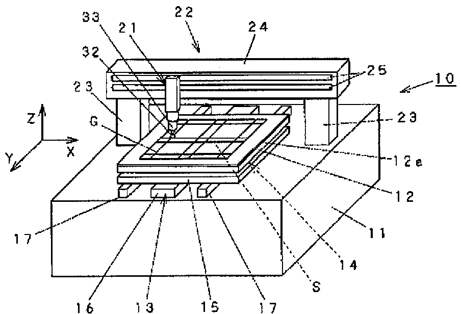
[0046] (fracture device) figure 1 It is a figure which shows the whole structure of the breaking apparatus 10 used when carrying out the breaking method of this invention. A scribing table 12 on which a substrate G is placed is provided on the base 11 . The scribing table 12 includes a Y-axis driving mechanism 13 for moving in the Y direction, and a scribing table rotating mechanism 14 installed below the scribing table 12 to rotate the scribing table 12 . Rubber 12a is laid on the upper surface of the scribing table 12, and when a load is applied to the substrate G from above, the substrate G is easily bent. The Y-axis drive mechanism 13 includes a Y stage 15 that supports the scribe table 12 via a scribe table rotation mechanism 14 , a linear motor 16 that drives the Y stage 15 in the Y direction, and ...
PUM
 Abstract
Description
Claims
Application Information