Brake controller for bicycle pedal brake device

A brake device and brake control technology, which is applied in the field of brake controllers in bicycle pedal brake devices, can solve the problems of long wires exposed outside, difficult to carry, and complex structure of reverse brake mechanisms, so as to avoid potential safety hazards and improve brake safety. Improved effect

Inactive Publication Date: 2012-07-25
张建民
View PDF5 Cites 2 Cited by
  • Summary
  • Abstract
  • Description
  • Claims
  • Application Information

AI Technical Summary

Problems solved by technology

[0002] In the existing bicycles, the braking devices of the bicycle are mostly manual pull-wire brakes and manual hydraulic transmission brakes, which are generally composed of a brake control mechanism, a transmission line and a brake brake. The transmission line can be a brake line or an oil brake. The pressure tube and the brake control mechanism are connected to the brake brake installed on the wheel through the transmission line. Most of the brake control mechanism is a hand brake, which is installed on the handlebar tube of the bicycle. When braking, both hands need to hold the brake lever tightly and tighten the brake. Line or drive hydraulic pump transmission to implement braking, and a small number of brake control mechanisms use reverse brake mechanism, which is composed of chain drive mechanism and overrunning clutch, and brake brake is composed of agitation mechanism and brake expansion sleeve, among which, overrunning clutch and brake The brakes are all installed in the hub of the rear wheel. The chain drive mechanism includes a sprocket chain drive mechanism and a pedal mechanism installed at the central axis tube under the frame to drive the sprocket to rotate. When braking, step on the pedal to drive the chain to drive and overtake The clutch is used to release the linkage relationship between the chain drive mechanism and the hub, and at the same time let the agitating mechanism cause the brake expansion sleeve to expand and contact the inner wall of the hub to cause friction, thereby slowing down or stopping the rear wheel. The structure of the mechanism is relatively complicated, and only the rear wheels can be braked, and the brakes of the front wheels still need to be braked by the hand brake.
In addition, if the existing above-mentioned several braking methods are used on a foldable bicycle, since the backguy is drawn from the horizontal tube, it is divided into the front and rear wheels along the standpipe and the frame tube. When the cross tube and the stem tube are usually shrunk and folded, the brake cable or oil pressure tube can neither be folded nor wound, and the long line is exposed, which makes the folded car untidy and difficult to carry. Hooked objects can also be dangerous

Method used


Image

  • Brake controller for bicycle pedal brake device
  • Brake controller for bicycle pedal brake device
  • Brake controller for bicycle pedal brake device

Examples


Embodiment 1

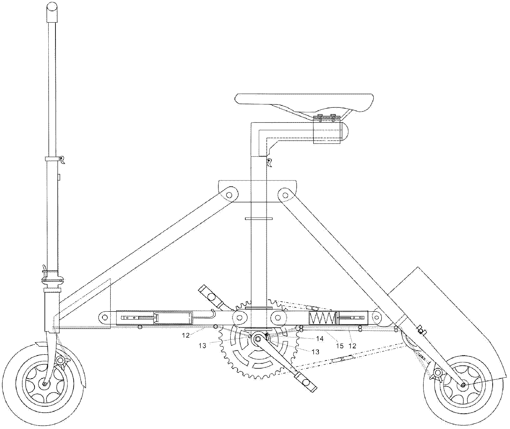
[0044] The embodiment of the brake controller in a bicycle pedal brake device of the present invention is the same as Figure 1 to Figure 7 As shown, the brake controller is used in figure 1 As shown in the electric bicycle, the braking method of the electric bicycle is a reverse disc brake. The brake controller is mainly composed of a brake ratchet mechanism, a brake control line 12 and a torsion spring 6. The brake ratchet mechanism includes a brake ratchet mechanism arranged under the frame The cylindrical brake wire fixing tube 5 in the bottom bracket tube 2 is sleeved in the middle of the bottom bracket 1 of the pedal, and combined with the bottom shaft 1 to form a brake ratchet mechanism, the bottom bracket tube 2 The two ends of the tube are sealed with flanges 4 with external threads, and the nozzles at both ends of the bottom bracket tube 2 have internal threads. The flange 4 covers the bottom bracket 1, and is threaded with the bottom bracket tube 2, and the brake cabl...

Embodiment 2

[0051] The second embodiment of the brake controller in a bicycle pedal brake device of the present invention is as Picture 9 , Picture 10 As shown, the difference from the first embodiment is that the brake controller of this embodiment does not include the power-off bungee cord 19, and the other structure is the same as that of the first embodiment. The brake controller is suitable for various types of bicycles that require braking. Just step on the pedal when you fall down.

Embodiment 3

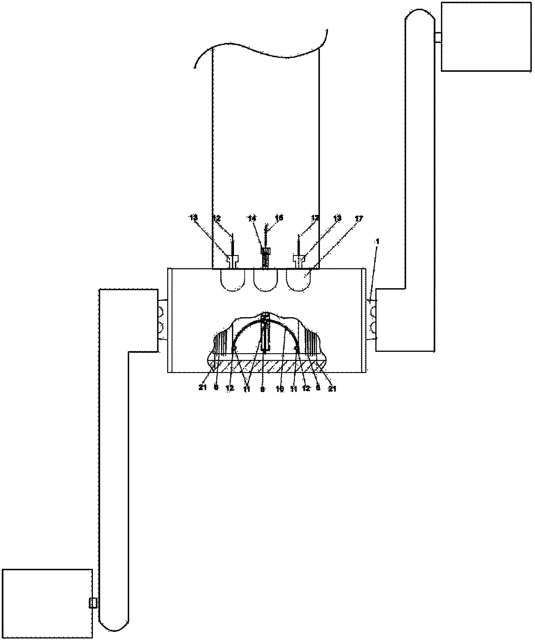
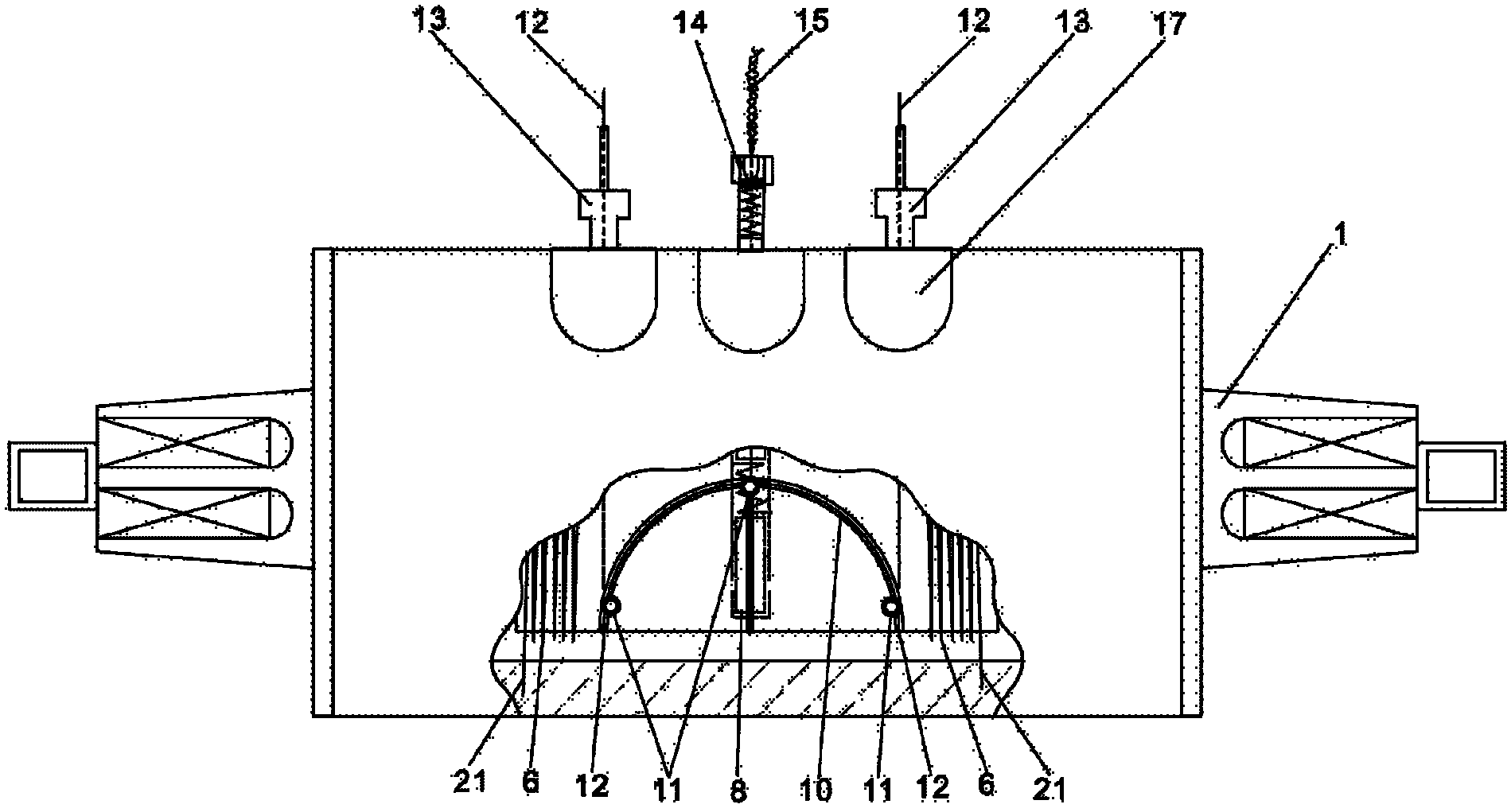
[0053] The third embodiment of the brake controller in a bicycle pedal brake device of the present invention Picture 11 , Picture 12 As shown, the difference from the first embodiment is that a spring 7 and a single pin 8 are used in the brake ratchet mechanism in this embodiment. The specific structure is: the center shaft 1 is opened in the center along the radial direction. Axle hole, the center axis hole is a blind hole 23, the bottom of the center axis hole is provided with a spring 7, in the center axis hole is placed a single body that can shrink into the hole under the action of external force and can extend out of the hole after the external force is eliminated The pin 8, the single pin 8 is suspended above the spring 7, the single pin 8 is the pawl in the brake ratchet mechanism, and the brake wire fixing tube 5 is radially on the inner wall surface on the same circumferential surface as the central shaft hole There are six equally divided gear teeth 9 with the same ...


PUM


Abstract

The invention discloses a brake controller for a bicycle pedal brake device, which mainly comprises a braking ratchet mechanism, brake cables and torsion springs. The braking ratchet mechanism comprises a cylindrical brake cable fixing tube which is arranged in a middle shaft tube below a frame and fixedly sleeved in the middle of a middle shaft, the cylindrical brake cable fixing tube is combined with the middle shaft to form the braking ratchet mechanism, the brake cables are arranged on the outer wall of the brake cable fixing tube and extend out of the middle shaft, the braking ratchet mechanism is in linkage with the middle shaft and used for winding and tightening the brake cables so as to pull braking brakes on a front wheel and a rear wheel to brake when a rider reversely pedals, and is not in linkage with the middle shaft when the rider forwardly pedals, the torsion springs are sleeved outside the brake cable fixing tube, and one end of each torsion spring is connected with the middle shaft tube while the other end of each torsion spring is fixed onto the brake cable fixing tube. The brake controller realizes braking of the front wheel and the rear wheel by reversely pedaling, is simple and direct in brake pedaling actions and safe and reliable in braking.

Description

Technical field [0001] The invention relates to a component in a bicycle pedal brake device, in particular to a brake controller in a bicycle pedal brake device. Background technique [0002] Among the existing bicycles, the brake devices of bicycles are mostly manual cable brake brakes and manual hydraulic transmission brakes, which are generally composed of a brake control mechanism, a transmission line and a brake brake. The transmission line can be a brake line or an oil The pressure tube, the brake control mechanism is connected to the brakes installed on the wheels through the transmission line. Most of the brake control mechanisms are hand brakes and are installed on the handlebar tube of the bicycle. When braking, you need to hold the brake lever with both hands to tighten the brake. Line or drive hydraulic pump drive to implement braking, and a small number of brake control mechanisms use reverse brake mechanism, which is composed of chain drive mechanism and overrunning...

Claims


Application Information

Patent Timeline
Patent Type & Authority Applications(China)
IPC IPC(8): B62L3/04B62L3/08
Inventor 张建民
Owner 张建民
Why Eureka
Try Eureka