Ball valve base structure with anti-block pre-tensioning device

An anti-jamming and valve seat technology, which is applied to cocks, valve devices, engine components, etc. including cut-off devices, can solve the problems of low material utilization and high manufacturing costs

Inactive Publication Date: 2012-07-25
CHAODA VALVE GRP
View PDF8 Cites 2 Cited by
  • Summary
  • Abstract
  • Description
  • Claims
  • Application Information

AI Technical Summary

Problems solved by technology

[0005] like figure 2 As shown, when the disc spring 4' is used, the disc spring 4' needs to be made of sheet material, because the utilization rate of the material is very low when the disc spring 4' is made of the plate, in addition, in order to improve the elasticity and Intensity, usually requires multiple disc springs 4' to be stacked together, so the manufacturing cost of disc springs 4' is relatively high

Method used


Image

  • Ball valve base structure with anti-block pre-tensioning device
  • Ball valve base structure with anti-block pre-tensioning device
  • Ball valve base structure with anti-block pre-tensioning device

Examples


Embodiment Construction

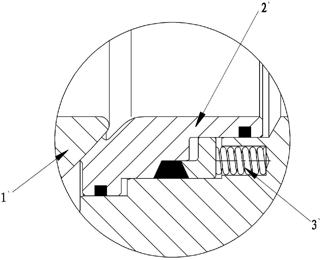
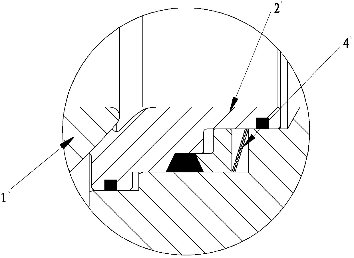
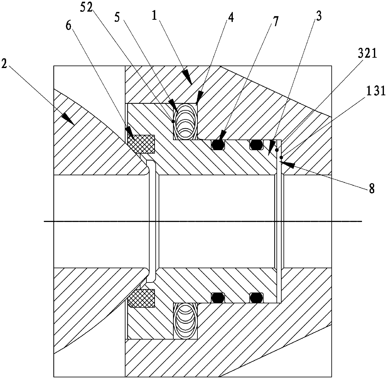
[0020] Such as image 3 — Figure 5 The seat structure of a ball valve with an anti-seize pre-tightening device shown includes a valve body 1, a ball 2 disposed in the valve cavity of the valve body 1, and a valve seat 3 that is in sealing fit with the ball 2. The valve body 1 There is an annular buffer chamber 4 between the valve seat 3. It should be noted that the buffer chamber 4 is formed after the valve body 1 and the valve seat 3 are installed and combined; the annular buffer chamber 4 is provided with an anti-seize device The anti-seize device includes a helical elastic ring 5 formed by a steel wire around the annular buffer chamber 4, and a number of contact points on both sides of the helical elastic ring 5 are in elastic contact with the valve seat 3 and the valve body 1 respectively. Cooperate. In the above scheme, a buffer chamber 4 is provided between the valve body 1 and the valve seat 3, and a spiral elastic ring 5 wound by a steel wire is arranged in the buff...


PUM


Abstract

The invention relates to a ball valve and particularly relates to a ball valve base structure with an anti-block pre-tensioning device. The technical scheme is that the ball valve base structure comprises a valve body, a ball body arranged in a valve cavity of the valve body and a valve seat matched with the ball body in a sealing mode, an annular relief chamber is arranged between the valve body and the valve seat, an anti-block tensioning device is arranged in the annular relief chamber, the anti-block tensioning device comprises a heliciform elastic ring formed by steel wires in a winding mode and arranged around the annular relief chamber, and a plurality of touch pints on two sides of the heliciform elastic ring are respectively matched with the valve seat and the valve body in an elastic abutting contact mode. By means of the technical scheme, the ball valve base structure with the anti-block pre-tensioning device can prevent solid media from blocking and is low in production cost.

Description

technical field [0001] The invention relates to a ball valve, in particular to a ball valve seat structure with an anti-seize pretension device. Background technique [0002] The ball valve came out in the 1950s. With the rapid development of science and technology, the continuous improvement of production technology and product structure, it has rapidly developed into a major valve category in just 40 years. In western industrially developed countries, the use of ball valves is increasing year by year. In my country, ball valves are widely used in petroleum refining, long-distance pipelines, chemicals, papermaking, pharmaceuticals, water conservancy, electric power, municipal, steel and other industries. occupies a pivotal position in the national economy. [0003] Such as figure 1 , figure 2 As shown, at present, in order to ensure the tight fit and seal between the ball 1' and the valve seat 2' of the fixed ball valve, a spring is usually arranged behind the valve sea...

Claims


Application Information

Patent Timeline
Patent Type & Authority Applications(China)
IPC IPC(8): F16K5/20
Inventor 邱晓来黄明金王汉洲叶建伟林洁兰文武潘建瓯唐成泽胡志安
Owner CHAODA VALVE GRP
Why Eureka
Try Eureka