Pipeline flow-velocity imaging and flow measuring method based on ultrasonic

A flow measurement, ultrasonic technology, applied in the direction of fluid velocity measurement, measurement of flow/mass flow, liquid/fluid solid measurement, etc.

Inactive Publication Date: 2012-07-25
TSINGHUA UNIV
View PDF4 Cites 32 Cited by
  • Summary
  • Abstract
  • Description
  • Claims
  • Application Information

AI Technical Summary

Problems solved by technology

[0004] In order to overcome the above-mentioned defects in the prior art, the object of the present invention is to provide a pipeline flow velocity imaging and flow measurement method based on ultrasonic w

Method used


Image

  • Pipeline flow-velocity imaging and flow measuring method based on ultrasonic
  • Pipeline flow-velocity imaging and flow measuring method based on ultrasonic
  • Pipeline flow-velocity imaging and flow measuring method based on ultrasonic

Examples


Embodiment Construction

[0028] The present invention will be described below in conjunction with the accompanying drawings.

[0029] A pipeline flow velocity imaging and flow measurement method based on ultrasound, comprising the following steps:

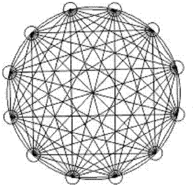
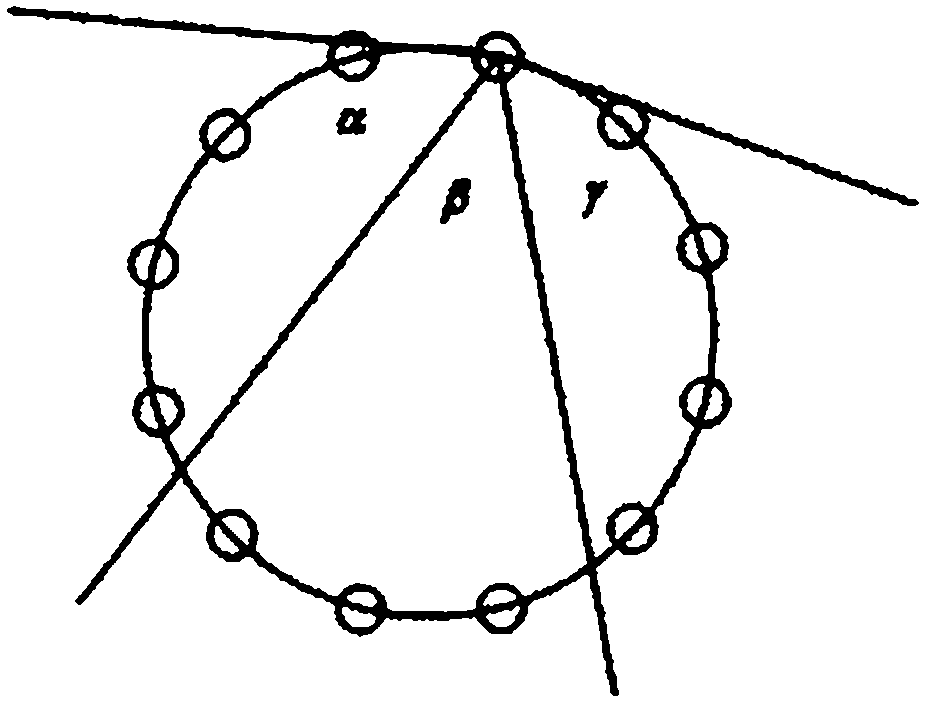
[0030]Step 1: Manufacture an ultrasonic probe composed of three piezoelectric units for transmitting and receiving ultrasonic signals. Each piezoelectric unit can complete the task of transmitting and receiving ultrasonic waves. Each piezoelectric unit has a certain sound beam angle , the sound beam angle satisfies the condition that the sound beam angle of the boundary piezoelectric unit involves the four adjacent probes respectively, and the sound beam angle of the central unit involves the three probes directly opposite;

[0031] Figure 2b is the placement form of the three piezoelectric units in the ultrasonic probe, α, β, and γ are the sound beam angles of each unit, Figure 2a Other ultrasonic probes within the beam angle coverage of each piezoele...


PUM


Abstract

Provided is a pipeline flow-velocity imaging and flow measuring method based on ultrasonic. Ultrasonic probes composed of three piezoelectricity units are processed and used for sending and receiving ultrasonic signals. The ultrasonic probes are respectively arranged on two oblique sections which form 45 degrees with the pipeline axis, measure flight time of fair-current and adverse-current transmission of the ultrasonic on each sound track and calculate average flow velocity of pipeline fluid on each sound track. Uniformly-spaced interpolation is performed to each group of sound tracks, the average flow velocity on each sound track after interpolation is obtained, the flow velocity distribution profile is rebuilt from average flow velocity data on the basis of a filtering back projectionmethod of parallel beam projection, flow velocity points are selected at a uniformly-spaced mode on the basis of a flow velocity distribution profile map obtained by rebuilding, and the flow velocityof each point is simply averaged and then multiplied with the sectional area of the pipeline so that pipeline flow values are obtained. The pipeline flow-velocity imaging and flow measuring method based on the ultrasonic can monitor distribution of flow field in the pipeline under complex flow state and reduces model errors of an ultrasonic flowmeter, and the accurate flow values are obtained finally.

Description

technical field [0001] The invention relates to the technical field of applying information science to high-precision measurement of internal fluid flow in a pipeline transportation system, in particular to an ultrasound-based pipeline velocity imaging and flow measurement method. Background technique [0002] The transit-time ultrasonic flowmeter is non-contact, has no moving parts, is insensitive to fluid characteristics, and is suitable for large-caliber applications. Pipelines and other advantages can be widely used in large-scale water conservancy projects, oil industry and natural gas industry. However, in many practical applications, some special installation conditions will cause changes in the flow field in the pipeline, forming a complex flow velocity distribution profile. The model error of flow conversion under complex flow velocity profile is one of the most important factors affecting the accuracy of ultrasonic flowmeter. [0003] In order to use the ultrason...

Claims


Application Information

Patent Timeline
IPC IPC(8): G01F1/66G01P5/24
Inventor 王伯雄崔园园柳建楠罗秀芝
Owner TSINGHUA UNIV
Why Eureka
Try Eureka