
Ultrasonic detecting device and detecting method for interface corrugation of explosive welding composite material

A composite material and explosive welding technology, which is applied in the direction of analyzing solids and materials using sound waves/ultrasonic waves/infrasonic waves, and material analysis using sound waves/ultrasonic waves/infrasonic waves. It can solve the problems of high equipment cost, slow scanning speed, and the location of scanning devices Accuracy requirements are very high, to achieve the effect of high system reliability and fast detection speed

Active Publication Date: 2012-07-25
上海斌瑞检测技术服务有限公司
View PDF4 Cites 9 Cited by
  • Summary
  • Abstract
  • Description
  • Claims
  • Application Information

AI Technical Summary

Problems solved by technology

[0002] At present, the existing technology uses a high-frequency focusing probe to perform two-dimensional C-scan ripple imaging to detect the quality of the explosive welding process. The main problems of this technology are: the scanning speed is slow, and the position accuracy of the scanning device is very high, so the equipment cost At the same time, due to the slow scanning speed, in many cases it can only be used for laboratory testing and cannot be used for quality inspection in the production process

Method used

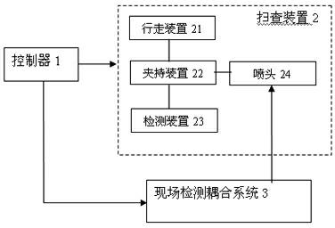
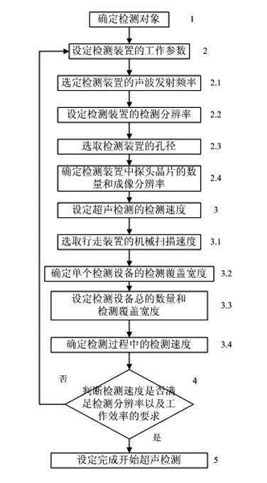
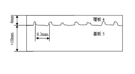

Image

  • Ultrasonic detecting device and detecting method for interface corrugation of explosive welding composite material
  • Ultrasonic detecting device and detecting method for interface corrugation of explosive welding composite material
  • Ultrasonic detecting device and detecting method for interface corrugation of explosive welding composite material

Examples


Embodiment Construction

[0042] Embodiments of the present invention will be described in detail below in conjunction with the accompanying drawings.

[0043] The invention discloses a high-frequency ultrasonic detection method for interface ripples of explosive welding composite materials. The detection technology adopted in the method is ultrasonic phased array technology, and the detection equipment adopts a phased array ultrasonic detection device. According to the thickness of the composite cladding and the resolution requirements of corrugated imaging, different excitation / receiving apertures and focusing laws are used to meet the requirements of different cladding thickness and detection resolution by controlling the focal depth and focal column diameter of the detection acoustic beam.

[0044] Ultrasonic phased array technology combines ultrasonic phased array technology and phased array ultrasonic detection technology.

[0045] According to the characteristics of various detection methods and...


PUM


Abstract

The invention discloses a detecting method for an ultrasonic detecting device for interface corrugations of an explosive welding composite material. The method comprises the following steps of 1. determining a detected object, wherein the detected object is a composite material and comprises a coating plate and a base plate which are composited together; 2. setting working parameters of the detecting device; 3. setting detecting speed of ultrasonic detection on the interface corrugations of the explosive welding composite material; 4. judging whether set detecting speed meets requirements on detection resolution ratio and work efficiency; and 5. carrying out the ultrasonic detection on the interface corrugations of the explosive welding composite material after a technique design is finished. The detecting method provided by the invention uses a high-frequency phased array ultrasonic detection technology so as to obtain detection images with high resolution ratio, and only high-precision mechanical scanning in the one-dimensional direction is required, so that the reliability of a system is high; a phased array probe is used to flexibly adjust the depth of focusing and the focusing column diameter of a detected wave beam through implementing different focusing rules; and therefore, flexible detection techniques on products with different parameters can be formulated.

Description

technical field [0001] The invention relates to a detection technology for evaluating the quality of an explosive welding process, in particular to an ultrasonic detection device and a detection method for the interface ripple of an explosive welding composite material. Background technique [0002] At present, the existing technology uses a high-frequency focusing probe to perform two-dimensional C-scan ripple imaging to detect the quality of the explosive welding process. The main problems of this technology are: the scanning speed is slow, and the position accuracy of the scanning device is very high, so the equipment cost At the same time, due to the slow scanning speed, it can only be used for laboratory testing in many cases and cannot be used for quality inspection in the production process. Contents of the invention [0003] The invention provides an ultrasonic detection device and detection method for the interface corrugation of explosive welding composite materi...

Claims


Application Information

Patent Timeline
IPC IPC(8): G01N29/06G01N29/24
Inventor 廉国选
Owner 上海斌瑞检测技术服务有限公司
Learn More