Optimization design method of radial-flow-type hydraulic turbine

An optimized design, hydraulic turbine technology, applied in the direction of instrument, adaptive control, control/regulation system, etc., can solve the problem of limited theoretical data for the design of radial hydraulic turbine through-flow components, etc., to improve the optimization efficiency , improve the accuracy and ensure the effect of calculation accuracy

Active Publication Date: 2012-07-25
开山(西安)透平机械有限公司
View PDF7 Cites 28 Cited by
  • Summary
  • Abstract
  • Description
  • Claims
  • Application Information

AI Technical Summary

Benefits of technology

The patent text describes a co-evolution algorithm that can optimize multi-variable and highly nonlinear problems. It divides the problem into smaller sub-problems based on variable correlations, reducing the amount of calculation needed for optimization. The algorithm also uses a dynamic sampling strategy to update an approximate model, improving the accuracy of the model in the potential optimal region and increasing optimization efficiency. Additionally, the optimization process includes calling a physical property subroutine to ensure calculation accuracy and the ability to design expanders with different working fluids. The algorithm also considers the influence of various components on the flow field and performance of the whole machine, optimizing each component's work in the optimal state. The algorithm integrates with a CFD analysis program, automating the process and improving efficiency.

Problems solved by technology

This patented technical problem addressed in this patents relates to improving the performance and durability of hydroelectric turbochargers (HYT) during certain periods when there're very little oil being produced from them without causing excessive power loss. Current methods involve replacing expensive vane type water wheels at once every few hours, but these techniques have limitations like slow response times caused by viscosity changes over time and require frequent replacements leading to decreased lifetimes compared to alternative solutions. Therefore, new designs aimed towards efficient use of space within the engine compartment while maintaining reliable functionality.

Method used


Image

  • Optimization design method of radial-flow-type hydraulic turbine
  • Optimization design method of radial-flow-type hydraulic turbine
  • Optimization design method of radial-flow-type hydraulic turbine

Examples


Embodiment Construction

[0110] In order to facilitate the implementation of the present invention, the present invention will be further described in detail below in conjunction with the accompanying drawings and equations.

[0111] First, combining the unary optimization model described by equation (1) with the optimization algorithm, considering various constraints, solving the optimization problem through programming, and determining the impeller inlet and outlet diameters, velocity triangle, etc., are the basis for the three-dimensional design of flow components.

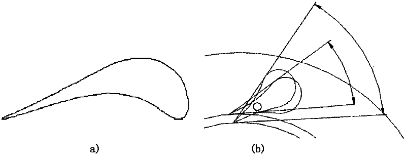
[0112] Second, based on the unary optimization design results, the initial shape of the flow-through components is designed, including the nozzle guide vane shape, impeller meter, and volute design. For hydraulic turbines operating at a fixed flow rate, it is recommended to use a fixed-installation angle nozzle structure, and the guide vane adopts an aerodynamic blade shape to reduce flow loss, such as figure 1 (a) shown. For the hydr...


PUM


Abstract

The invention discloses an optimization design method of a radial-flow-type hydraulic turbine. In the design method, a unitary thermal optimization design, a three-dimensional modeling method of a through-flow part and a complete machine optimization platform are utilized, wherein the optimization platform comprises four modules, namely nozzle blade and impeller blade parameterization, a coevolution genetic algorithm, a self-adaption approximation model, and autocall of CFD (computational fluid dynamics). Through the parameterization, characteristic variables describing impeller blades, nozzle blade patterns and installation angle variation are extracted. The optimization target is to enhance the overall efficiency and expansion ratio of the hydraulic turbine simultaneously under a complete machine environment. The optimization platform can be used for reducing the calculated amount and accelerating the convergence by virtue of the following measures: the approximation model is built and updated by a dynamic sampling strategy, and enough prediction accuracy is obtained by virtue of less CFD calculation; and a complicated multivariable optimization problem is decomposed into a plurality of relatively independent and interactive subproblems by virtue of the coevolution genetic algorithm, so that not only can the characteristics of the original problem be maintained, but also the calculated amount is reduced effectively.

Description


Claims


Application Information

Patent Timeline
Owner 开山(西安)透平机械有限公司
Why Eureka
Try Eureka