

Multi-angle image acquisition device and multi-angle optical characteristic detection equipment
An image acquisition device and optical feature technology, which is applied in image communication, banknote authenticity inspection, color TV parts, etc., can solve the problem that it is difficult to collect high-resolution images, the detection effect is difficult to guarantee, and the processing technology is complicated. and other issues, to achieve the effect of mature production technology, low cost and high acquisition rate
- Summary
- Abstract
- Description
- Claims
- Application Information
AI Technical Summary
Problems solved by technology
Method used
Image

Examples
Embodiment 1
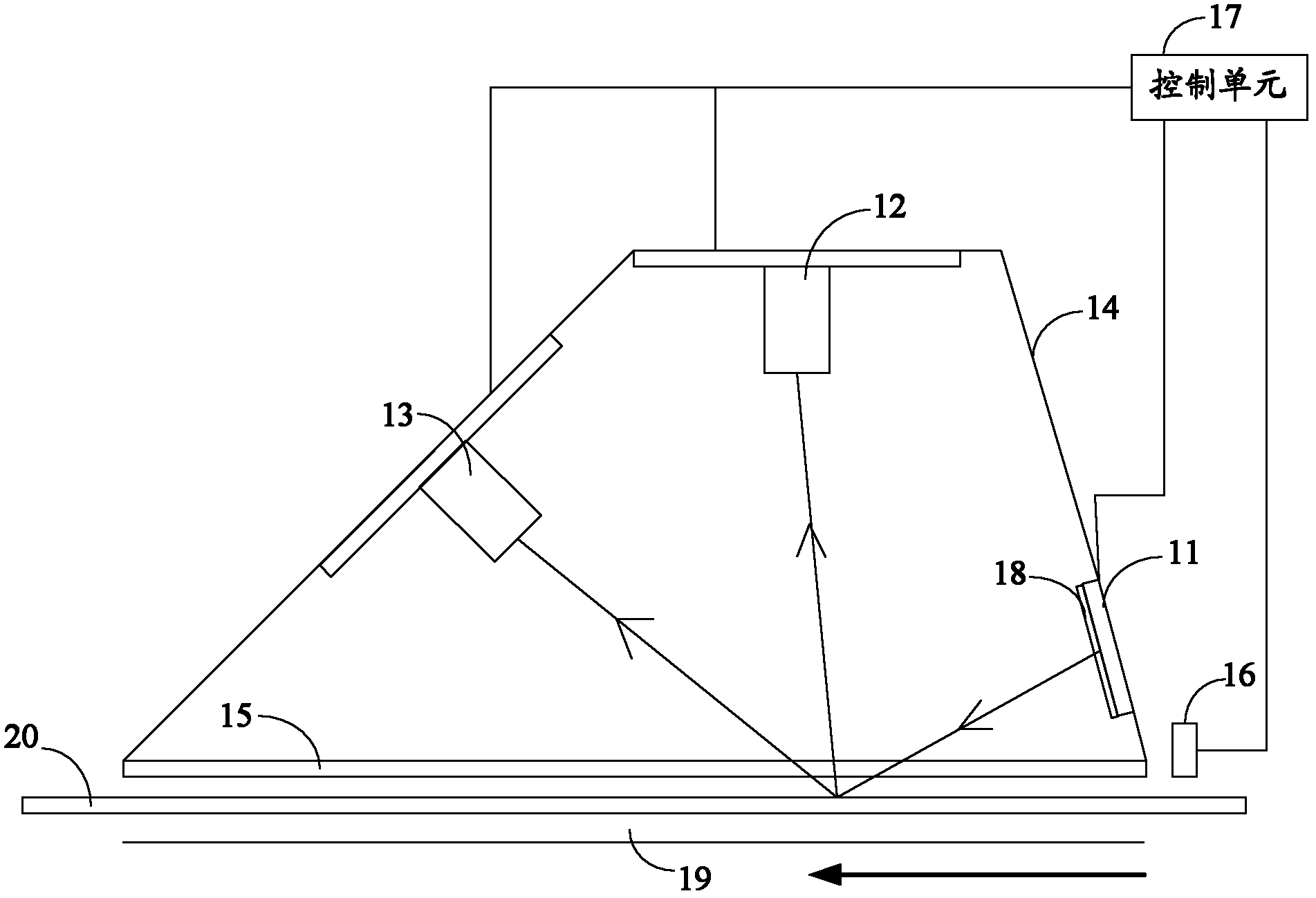
[0067] figure 1 It is a structural schematic diagram of the first multi-angle image acquisition device in the embodiment of the present invention, which includes: a light source 11, a first camera 12, a second camera 13, a housing 14, a glass plate 15, a position sensor 16, and a control unit 17 and polarizer 18. figure 1 The analyte conveying channel in is marked with 19, the analyte is marked with 20, and the thick solid arrow indicates the conveying direction of the analyte.
[0068] The position sensor 16 is located at the starting end of the conveying direction of the detected object, and sends a signal to the control unit 17 after detecting that the area to be detected on the detected object 20 reaches the detection position. The position sensor 16 has a variety of methods for detecting the position. For example, assuming that the detected object 20 passes through the set distance from entering the detected object conveying channel 19, its area to be detected will reach...
Embodiment 2
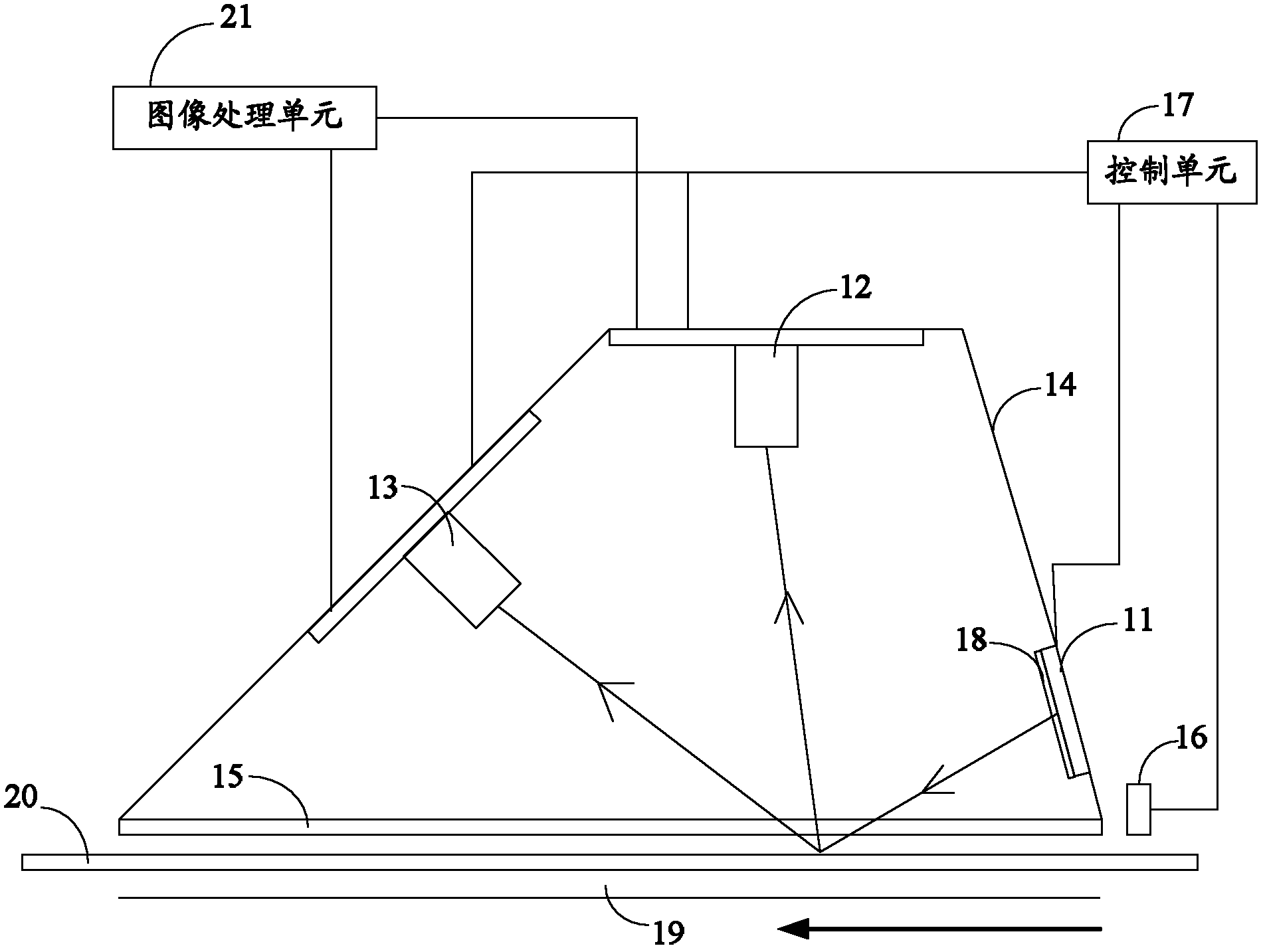
[0081] figure 2 It is a schematic structural diagram of the first multi-angle optical feature detection device in the embodiment of the present invention. It can be seen that, figure 2 is in figure 1 An image processing unit 21 is added on the basis, and the image processing unit 21 is connected with the data interface of the first camera 12 and the data interface of the second camera 13, receives the images collected by the first camera 12 and the second camera 13, and compares them, To determine whether there are multi-angle optical features in the area to be detected.
[0082] The second multi-angle image acquisition device provided by the present invention includes at least two image acquisition units, wherein at least one image acquisition device is located on one side of the transport channel of the detected object, and at least one other image acquisition device is located on the transport channel of the detected object On the other side, each image acquisition unit...
Embodiment 3
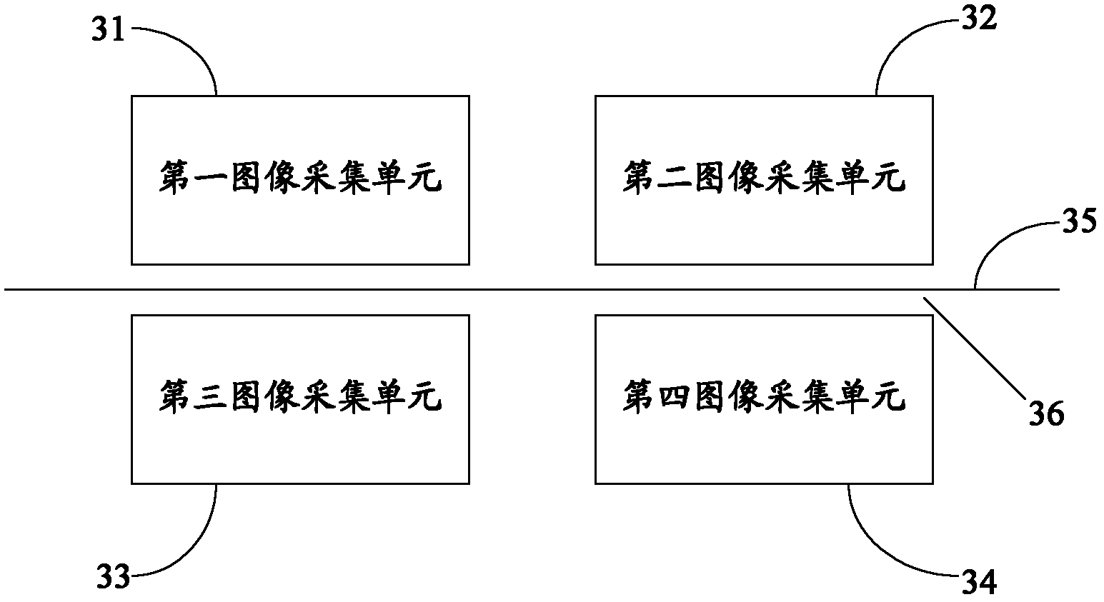
[0090] image 3 It is a schematic structural diagram of the second multi-angle image acquisition device in the embodiment of the present invention, which includes a first image acquisition unit 31, a second image acquisition unit 32, a third image acquisition unit 33 and a fourth image acquisition unit 34 . image 3 The object to be tested is marked with 35, the conveying channel of the detected object is marked with 36, and the conveying direction of the detected object is perpendicular to the paper surface.
[0091] Figure 4 It is a schematic diagram of the position of the area to be detected on the object to be detected in the embodiment of the present invention. Taking the area to be detected as a color-changing ink area and the object to be detected as RMB as an example, a schematic diagram of the position of the color-changing ink on the RMB is given. For a piece of RMB (for example, the fifth edition of 100 yuan), the color-changing ink is located in the lower left c...
PUM
 Abstract
Description
Claims
Application Information