Device for generating electricity by collecting environmental low-grade energy source

A low-grade energy generation technology, applied in the direction of generators, generators/motors, and electrical components that convert kinetic energy into electrical energy, can solve problems such as low efficiency and high-grade pressure energy consumption

Inactive Publication Date: 2012-07-25
WUHAN UNIV
View PDF4 Cites 12 Cited by
  • Summary
  • Abstract
  • Description
  • Claims
  • Application Information

AI Technical Summary

Problems solved by technology

[0004] All previous nanochannel electric double layer power generation systems use high-grade pressure energy as the driving force to drive the electrolyte solution to flow through the nanochannel, but due to the

Method used


Image

  • Device for generating electricity by collecting environmental low-grade energy source
  • Device for generating electricity by collecting environmental low-grade energy source
  • Device for generating electricity by collecting environmental low-grade energy source

Examples


Embodiment 1

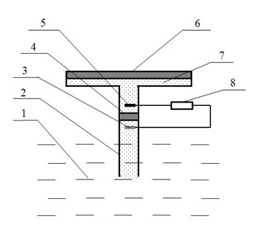
[0023] see figure 2 , a device for collecting low-grade energy from the environment to generate electricity, it includes a liquid inlet pipe 2 and a liquid storage chamber 7, the upward surface of the liquid storage chamber 7 is an evaporation film 6, and the liquid inlet pipe 2 and the liquid storage chamber 7 are connected by a nanochannel 4 ; There is an Ag electrode 3 in the liquid inlet pipe 2, and there is Ag in the liquid storage chamber 2 CO 3 or AgO electrode5, Ag electrode and Ag 2 CO 3 Or the AgO electrode is connected to the load or energy storage device 8 through wires.

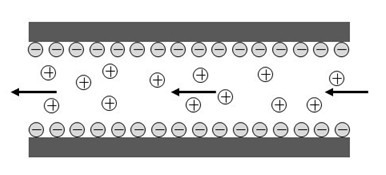
[0024] When working, the carbonic acid solution in the liquid storage chamber is continuously evaporated through the gas-liquid interface in the evaporation film, and the evaporation film is a nano- or micro-porous film. The capillary force generated by the evaporation film provides a continuous driving force for the evaporation of the carbonic acid solution. The electrical energy generated ...

Embodiment 2

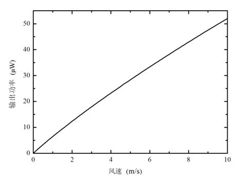
[0028] The use of wind energy. see figure 2 , the evaporation film is a nanoporous material with an area of ​​1 cm 2 , the concentration of the carbonic acid solution is 3×10 -4 mol / L, the nanochannel is composed of multiple parallel nanochannels with a length of 50μm, a width of 55nm, and a height of 4.5mm, and the number of channels is 5×10 4 . Under the environment of 25 degrees, different wind speeds of 0-10m / s are used to act on the evaporation film in parallel, and the structural features of other parts are the same as that of embodiment 1. Through calculation, it can be obtained that as the wind speed increases, the output power of the system increases. When the wind speed is 10m / s, the output power of the system is 52.1μW, see image 3 . The system has extremely high apparent wind energy utilization efficiency, the lower the wind speed, the higher the efficiency, which can reach more than 100%, see Figure 4 , indicating that the thermal energy in the environmen...

Embodiment 3

[0030] use of excess heat. see figure 2 , the evaporation membrane material is a nanoporous material with an area of ​​1 cm 2 , the concentration of the carbonic acid solution is 3×10 -4 mol / L. The nanochannel is composed of multiple parallel nanochannels with a length of 50 μm, a width of 55 nm, and a height of 4.5 mm. The number of channels is matched with the waste heat temperature to obtain the highest power generation. The different residual heats of 30 to 80 degrees act on the evaporation film, and the structural features of other parts are the same as in Embodiment 1. It can be obtained by calculation, see Figure 5 , as the waste heat temperature increases, the system output power increases. When the evaporation temperature is 80 degrees, the output power of the system is 55.4μW.


PUM

PropertyMeasurementUnit
Concentrationaaaaaaaaaa

Abstract

The invention relates to an environmental energy utilization system, in particular relates to an environmental low-grade energy utilization system by utilizing capillary force and a nanometer channel double electric layer effect, comprising a liquid feeding pipe, wherein the liquid feeding pipe is connected with a nanometer channel, two electrodes are closely adhered at two ends of the nanometer channel, and a middle liquid storage room is connected with the other side of the nanometer channel and is connected with an evaporation film. Electrolyte solution is driven by the capillary force generated by evaporation of liquid on the evaporation film to flow through the nanometer channel, and electricity generation is carried out on ion selection by utilizing the nanometer channel. The invention provides a new energy source utilizing method which is clean and high-efficiency and the great prospect on various energy aspects in a collection utilization environment can be realized.

Description

technical field [0001] The invention relates to an environmental energy utilization system, in particular to a device for collecting low-grade environmental energy and generating electricity by using capillary force and nano-channel electric double layer effect. Background technique [0002] In the context of the increasingly severe energy situation and environmental pollution, seeking clean and efficient energy conversion methods is the core content of current energy research work, especially the recycling of low-grade energy has attracted more and more attention. There is a lot of energy in the environment we live in, including wind energy, solar energy and thermal energy, etc. Nowadays, the main ways to use solar power to generate electricity are photovoltaic power generation and solar thermal power generation, while the use of wind power to generate electricity mainly uses fans. Both solar power generation and wind power generation have the problem of sporadic and conti...

Claims


Application Information

Patent Timeline
IPC IPC(8): H02N3/00
Inventor 胡雪蛟刘抗黄志李昌铮
Owner WUHAN UNIV
Why Eureka
Try Eureka