
Eureka
For R&D, Eureka makes reading and utilizing patents & technical documents easy.
Eureka AIR
Designed for self-driven R&D workflows. Generate viable solutions, solve complex R&D challenges, empower your innovation with AI.

Eureka Materials
Designed for material experts only. Revolutionize your material R&D, from search, analyze, to developing new materials.

TechResearch
Generate reliable direction feasibility study reports for your R&D in just a few steps.

TechSeek
Discover and master advanced knowledge NOW. Basics, ideas, possibilities, all at once.

TechMind
As an expert in R&D Theories, TechMind can generates customized viable solutions instantly.

TechRisk
Analyze your overall solution with one click, know your potential R&D risks in advance.

TechMonitor
Get weekly tech updates, stay abreast of the latest tech innovations and key insights.
Ballast for low-frequency electrodeless lamp
A low-frequency electrodeless lamp and ballast technology, applied in the field of electronic ballasts, can solve the problems of insufficient driving voltage of a ballast MOS tube drive circuit, unable to obtain a 13.5V power supply voltage, etc., and achieves simple structure, reasonable design and cost. low cost effect
- Summary
- Abstract
- Description
- Claims
- Application Information
AI Technical Summary
Problems solved by technology
Method used
Image

Examples
Embodiment Construction
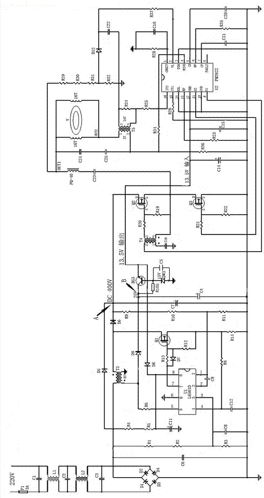
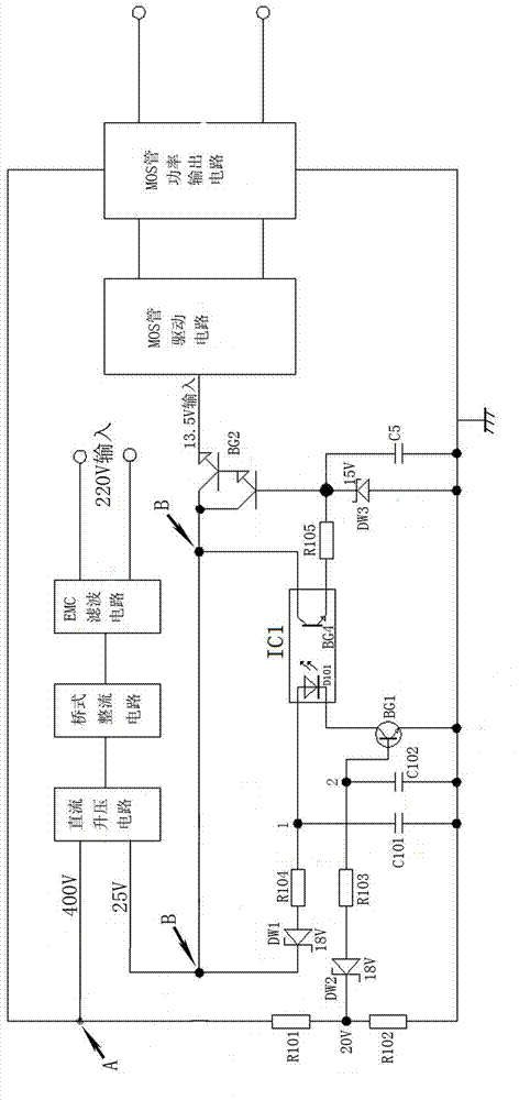
[0024] Combine below figure 1 and figure 2 The present invention will be described in detail.
[0025] A low-frequency electrodeless lamp ballast, including an EMC filter circuit, a bridge rectifier circuit, a DC boost circuit, a MOS tube drive circuit including an FM2822 chip U2, a MOS tube power output circuit, a third transistor BG3, and a 15V third stabilizer Pressure tube DW3, fifth capacitor C5, eighth crystal diode D8 and first and fifth resistor R105.
[0026] The DC step-up circuit includes an L6561D chip U1, a third high-frequency transformer T3, a first MOS transistor Q1, a sixth crystal diode D6, and a ninth crystal diode D9; wherein, one end of the primary winding of the third high-frequency transformer T3 is connected to the first The anode terminals of the six crystal diodes D6 are connected, and the cathode terminal of the sixth crystal diode D6 is the output terminal A of the DC booster circuit; one end of the secondary winding of the third high-frequenc...
PUM
 Abstract
Description
Claims
Application Information
 - R&D Engineer
- R&D Manager
- IP Professional
- Industry Leading Data Capabilities
- Powerful AI technology
- Patent DNA Extraction
Browse by: Latest US Patents, China's latest patents, Technical Efficacy Thesaurus, Application Domain, Technology Topic, Popular Technical Reports.
© 2024 PatSnap. All rights reserved.Legal|Privacy policy|Modern Slavery Act Transparency Statement|Sitemap|About US| Contact US: help@patsnap.com