Engine starting method and device, vehicle and storage medium

An engine start and engine technology, applied in the direction of engine control, machine/engine, mechanical equipment, etc., can solve the problems of multiple test injections and long time for successful engine start, and achieve the effect of ensuring fast start

Active Publication Date: 2021-05-11
WEICHAI POWER CO LTD
View PDF10 Cites 0 Cited by
  • Summary
  • Abstract
  • Description
  • Claims
  • Application Information

AI Technical Summary

Problems solved by technology

Based on the above-mentioned ECU control strategy, there may be a problem that the test injection may take several times, which will lead to a long time for the engine to start successfully, and the failure cannot be avoided

Method used


Image

  • Engine starting method and device, vehicle and storage medium
  • Engine starting method and device, vehicle and storage medium
  • Engine starting method and device, vehicle and storage medium

Examples


Embodiment 1

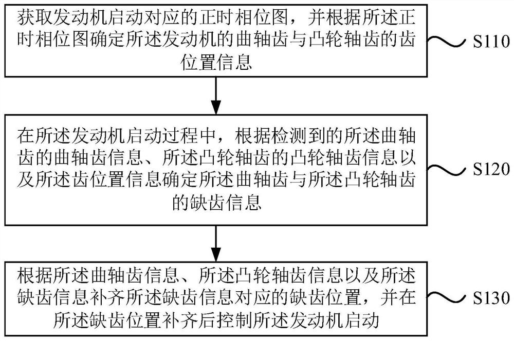
[0027] figure 1 It is a flow chart of an engine starting method provided by Embodiment 1 of the present invention. This embodiment is applicable to the situation that the engine starts quickly when the camshaft signal is lost. The method can be executed by the engine starting device, and the device can and / or in the form of hardware. Specifically include the following steps:

[0028] S110. Obtain a timing phase diagram corresponding to engine startup, and determine tooth position information of crankshaft teeth and camshaft teeth of the engine according to the timing phase diagram;

[0029] Among them, the timing phase is a necessary condition for the normal operation of the engine. The timing phase map is used in modern electronically controlled vehicles. The engine ECU uses the crankshaft position sensor, camshaft position sensor, etc. to detect the position of the crankshaft and camshaft to reflect whether If the fuel injection timing and ignition timing are correct, the ...

Embodiment 2

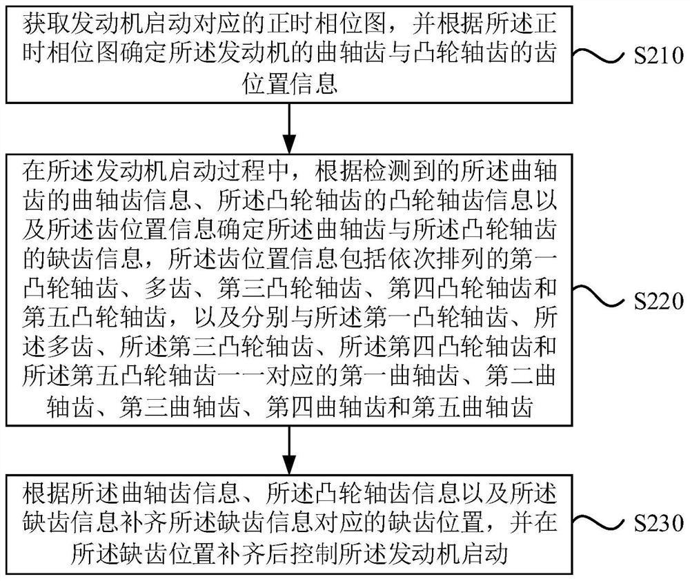
[0050] figure 2 It is a flow chart of an engine starting method provided by Embodiment 2 of the present invention, and this embodiment is optimized on the basis of the foregoing embodiments.

[0051] Correspondingly, the method in this embodiment specifically includes:

[0052] S210. Obtain a timing phase diagram corresponding to engine startup, and determine tooth position information of crankshaft teeth and camshaft teeth of the engine according to the timing phase diagram.

[0053] S220. During the starting process of the engine, determine the relationship between the crankshaft tooth and the camshaft tooth according to the detected crankshaft tooth information of the crankshaft tooth, the camshaft tooth information of the camshaft tooth, and the tooth position information. missing tooth information, the tooth position information includes the first camshaft tooth, multiple teeth, third camshaft tooth, fourth camshaft tooth and fifth camshaft tooth arranged in sequence, a...

Embodiment 3

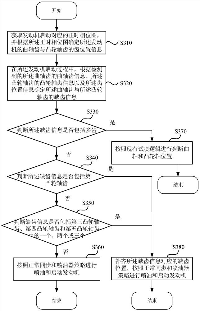
[0068] image 3 It is a schematic diagram of an engine starting method provided by Embodiment 3 of the present invention, and the technical solution of the embodiment of the present invention is further optimized on the basis of the foregoing embodiments. The method of this embodiment specifically includes:

[0069] S310. Obtain a timing phase diagram corresponding to engine startup, and determine tooth position information of crankshaft teeth and camshaft teeth of the engine according to the timing phase diagram.

[0070] S320. During the starting process of the engine, determine the relationship between the crankshaft tooth and the camshaft tooth according to the detected crankshaft tooth information of the crankshaft tooth, the camshaft tooth information of the camshaft tooth, and the tooth position information. dentition information.

[0071] S330. Determine whether the tooth-missing information includes multiple teeth, if yes, perform step S370, and if not, perform step S...


PUM


Abstract

An embodiment of the invention discloses an engine starting method and device, a vehicle and a storage medium. The method comprises the steps that a timing phase diagram corresponding to engine starting is obtained, and tooth position information of crankshaft teeth and camshaft teeth of an engine is determined according to the timing phase diagram; in the starting process of the engine, tooth missing information of the crankshaft teeth and the camshaft teeth is determined according to the detected crankshaft tooth information of the crankshaft teeth, the detected camshaft tooth information of the camshaft teeth and the tooth position information; and according to the crankshaft tooth information, the camshaft tooth information and the tooth missing information, the tooth missing position corresponding to the tooth missing information is supplemented, and after the tooth missing position is supplemented, the engine is controlled to be started. According to the technical scheme, the signal teeth corresponding to the camshaft are automatically supplemented, and quick starting of the engine is guaranteed.

Description

technical field [0001] Embodiments of the present invention relate to the technical field of engine control, and in particular, to an engine starting method, device, vehicle, and storage medium. Background technique [0002] At present, diesel engines are generally electronically controlled, that is, the position of the engine is judged by the ECU (Engine Electronic Control Unit). output power. [0003] In the process of starting the engine, when the engine speed is from zero to low idle speed, the relative position of the crankshaft and the camshaft is used to determine the current stroke of the engine, and then inject fuel. However, in the actual operation of the engine, due to the camshaft sensor Various reasons such as failure, improper assembly or deformation will cause the ECU to fail to collect the signal of one of the camshafts. The strategy currently adopted by the ECU is to report a camshaft signal error fault, determine that the camshaft signal is not credible, ...

Claims


Application Information

Patent Timeline
Patent Type & Authority Applications(China)
IPC IPC(8): F02D41/06F02D41/00F02D29/02F02D41/30
CPCF02D41/062F02D41/009F02D29/02F02D41/3005Y02T10/40
Inventor 秦涛孙明峰曹石李国朋
Owner WEICHAI POWER CO LTD
Why Eureka
Try Eureka