Ridger capable of forming ridge through overturn and reverse push

A ridge-building machine and ridge-building technology, applied in the fields of farming machines, agricultural machinery and tools, applications, etc., can solve the problems of affecting the working speed, inconvenient building ridges, inconvenient horizontal adjustment, etc., so as to improve the working speed and facilitate the horizontal adjustment , the effect of the same direction

Inactive Publication Date: 2012-08-01
崔春鹤
View PDF5 Cites 8 Cited by
  • Summary
  • Abstract
  • Description
  • Claims
  • Application Information

AI Technical Summary

Problems solved by technology

However, the existing ridge-building machines are all rear-hanging traction operations. It is inconvenient to build a ridge when advancing to the head of the field when building a ridge. , but the ridge built later is reversed, so that the consistency of the ridge cannot meet the requirements, and it will also affect the firmness of the ridge
In the operation of the existing ridge-building machine, when there is a lateral position deviation between the ridge-building wheel and the field ridge, it is inconvenient to adjust laterally. It needs to move laterally with the traction machine to adjust laterally. It is inconvenient to adjust and affects the working speed.

Method used


Image

  • Ridger capable of forming ridge through overturn and reverse push
  • Ridger capable of forming ridge through overturn and reverse push

Examples


Embodiment Construction

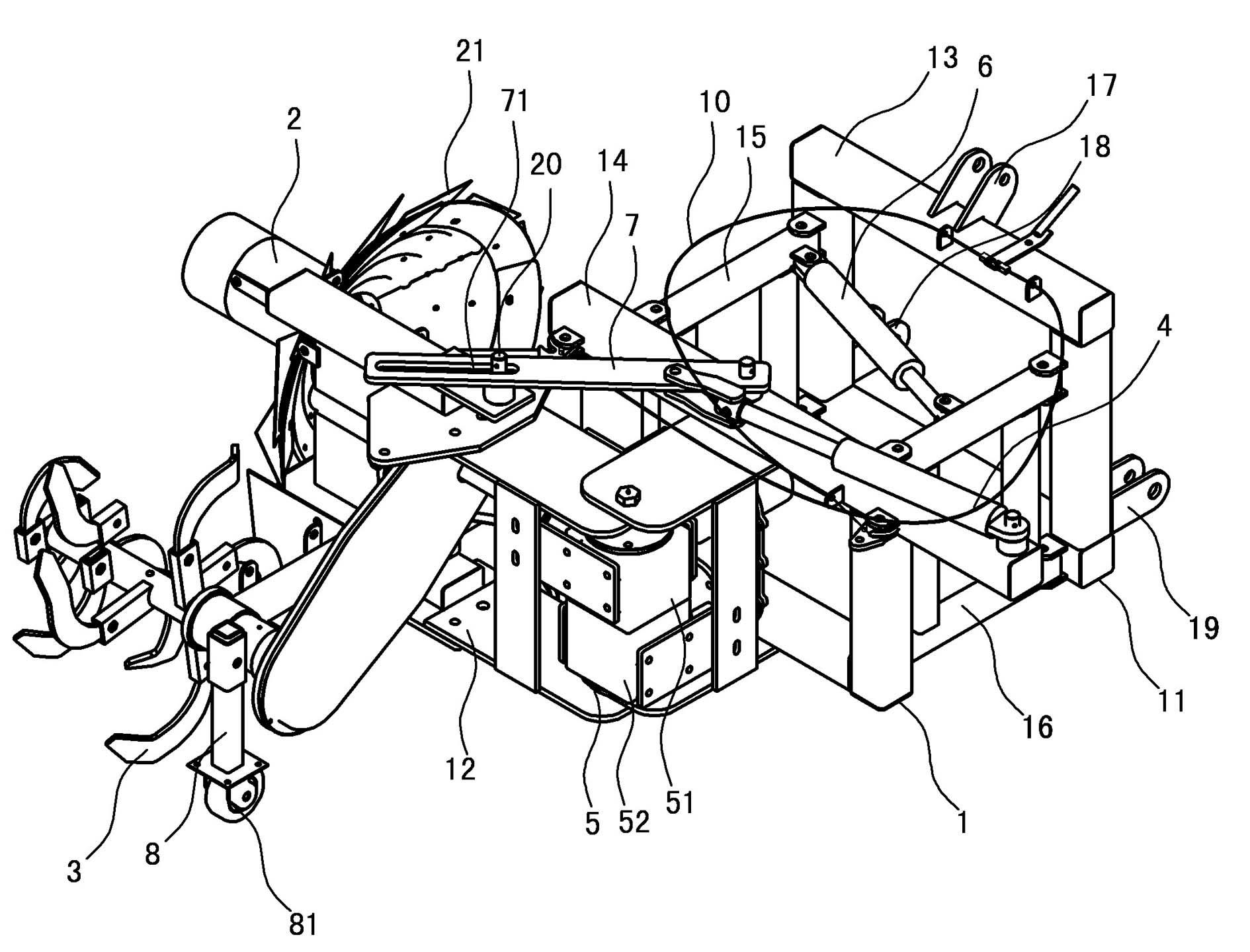
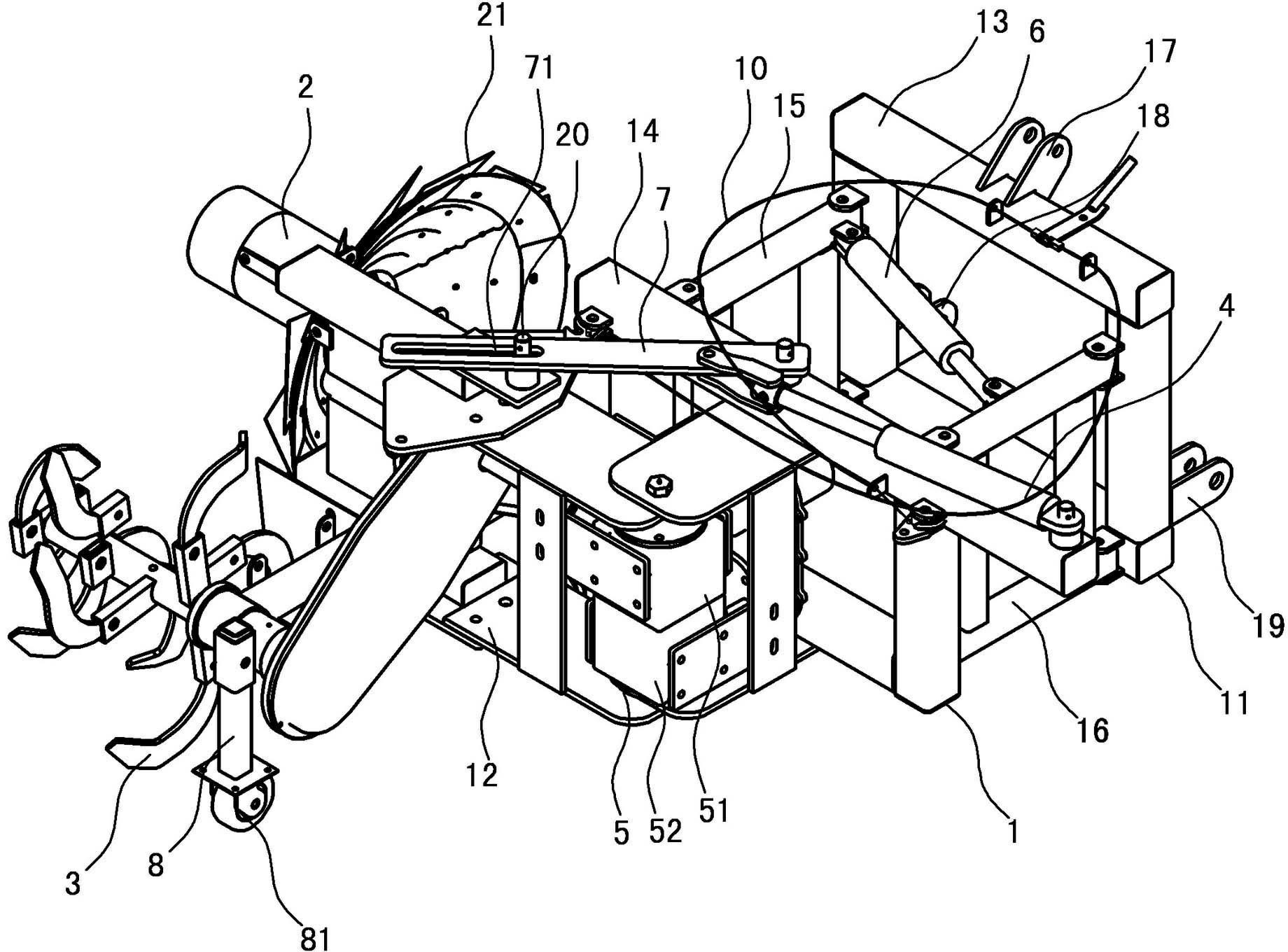
[0008] It also includes a gearbox 5 installed between the traction suspension frame 11 and the ridge frame 12 for rotary tillage. The upper box body 51 and the lower box body 52 are composed of two parts. The upper box body 51 is installed on the traction suspension frame 11, and the upper box body 51 is connected with the input shaft 53 connected with the tractor. The lower box body 52 is installed on the rotary tiller. The first output shaft and the second output shaft connected on the upper and lower boxes 52 of the ridge frame 12 are respectively connected with the ridge wheel 2 and the rotary tiller wheel 3 by chains.

[0009] The traction suspension frame 11 and the rotary tillage building ridge frame 12 can be locked to prevent the traction wire rope 10 from turning over automatically after the traction suspension frame 11 and the rotary tillage building ridge frame 12 are provided with the rotary tillage building ridge frame 12 and turned over and positioned.

[0010] ...


PUM


Abstract

The invention relates to a ridger capable of forming a ridge through overturn and reverse push. The ridger comprises a machine frame (1), a ridge forming wheel (2) and a rotary cultivating wheel (3), wherein the machine frame (1) is composed of a traction and suspension frame (11) and a rotary cultivating and ridge forming frame (12), the ridge forming frame (12) is hinged on the traction and suspension frame (11), and can overturn horizontally, an overturning oil cylinder (4) is arranged between the traction and suspension frame (11) and the rotary cultivating and ridge forming frame (12), and is used for controlling the overturn of the rotary cultivating and ridge forming frame (12), and the ridge forming wheel (2) and the rotary cultivating wheel (3) are respectively installed on the rotary cultivating and ridge forming frame (12). The ridger is convenient to form the ridge at a plot end and to adjust transversely; when a transverse deviation exists between the ridger and the ridge, the transverse adjustment can be carried out conveniently to increase operating speed; the ridge forming wheel (2) and the rotary cultivating wheel (3) can rotate 180 degrees on the suspension frame; the ridge at the plot end can be conveniently formed by using traction machinery to reversely push the ridge forming wheel and the rotary cultivating wheel to work; the formed ridges are consistent in direction; and solidity of the ridges cannot be affected.

Description

technical field [0001] The invention relates to agricultural machinery, in particular to a ridge building machine. Background technique [0002] The ridge building machine is an agricultural machine that can replace manual ridge building. It has the advantages of fast ridge building speed, high efficiency, and neat and beautiful ridges, and is widely popularized and applied. However, the existing ridge-building machines are all rear-hanging traction operations. It is inconvenient to build a ridge when advancing to the head of the field when building a ridge. , but the section of the ridge built later is reversed, so that the consistency of the ridge cannot meet the requirements, and it will also affect the firmness of the ridge. In the operation of the existing ridge-building machine, when there is a lateral position deviation between the ridge-building wheel and the field ridge, it is inconvenient to adjust laterally, and it needs to move laterally together with the tracti...

Claims


Application Information

Patent Timeline
Patent Type & Authority Applications(China)
IPC IPC(8): A01B33/00A01B33/08
Inventor 崔春鹤赵永清林玉海候纪刚王宗岐胡喜博
Owner 崔春鹤
Why Eureka
Try Eureka