Dual-purpose type welding working device

A working device and dual-purpose technology, applied in the direction of auxiliary equipment, welding equipment, auxiliary welding equipment, etc., can solve the problem of reducing the welding efficiency of U-shaped pipe 11 or straight pipe 12, increasing equipment costs, and increasing the number of U-shaped pipes 11 or straight pipes. 12 Placement time and other issues, to achieve the effect of saving placement time, saving working hours, and improving welding efficiency

Inactive Publication Date: 2012-08-01
FOSHAN SHENGAN REFRIGERATION FITTINGS
View PDF12 Cites 2 Cited by
  • Summary
  • Abstract
  • Description
  • Claims
  • Application Information

AI Technical Summary

Problems solved by technology

[0002] U-shaped pipe 11 or straight pipe 12 need to be fixed when welding, as figure 1 and figure 2 As shown, the welding table S1 of the U-shaped pipe 11 or straight pipe 12 in the prior art has only one U-shaped pipe 11 or straight pipe 12 placement hole, and only one U-shaped pipe 11 or straight pipe 12 can be placed in a single place, that is, The U-shaped pipe 11 or straight pipe 12 to be welded can only be welded after queuing up one by one and waiting to be placed on the welding workbench S1 of the U-shaped pipe 11 or straight pipe 12 with technology. The placement time of the tube 12 reduces the welding efficiency of the U-shaped tube 11 or the straight tube 12, and the production requires multiple single welding workbenches S1, which also increases the equipment cost

Method used


Image

  • Dual-purpose type welding working device
  • Dual-purpose type welding working device
  • Dual-purpose type welding working device

Examples


Embodiment Construction

[0018] In order for those skilled in the art to better understand the technical solutions provided by the present invention, the following description will be given in conjunction with specific embodiments.

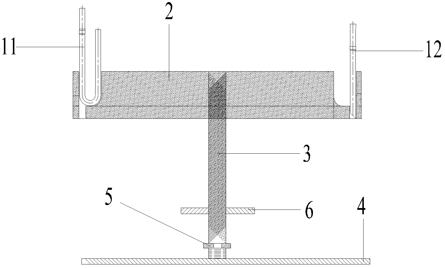
[0019] See image 3 with Figure 4 , image 3 It is a schematic diagram of the structure of a dual-purpose welding working device in an embodiment of the present invention; Figure 4 It is a schematic top view of a dual-purpose welding working device in an embodiment of the present invention.

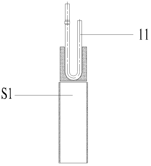
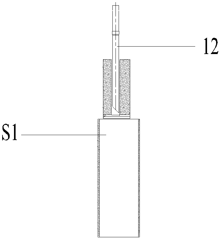
[0020] The dual-use welding working device provided by the embodiment of the present invention includes a base 4 and a placing table 2. The placing table 2 is connected to the base 4 through a mounting post 3, and the placing table 2 is provided with a U-shaped tube placing hole 7 and The straight pipe placement hole 8 and the U-shaped pipe placement hole 7 have an oval structure, and the straight pipe placement hole 8 has a circular structure.

[0021] The straight pipe placement hole ...


PUM


Abstract

The invention discloses a dual-purpose type welding working device, comprising a base and a placing table, wherein the placing table is connected onto the base by virtue of a mounting column, the placing table is provided with a U-shaped tube placing hole and a straight tube placing hole, the U-shaped tube placing hole is of an ellipse structure, and the straight tube placing hole is of a round structure. Compared with the prior art, the dual-purpose type welding working device disclosed by the invention can weld a U-shaped tube and / or a straight tube at the same time, operation is simper, efficiency is further improved, and the effects of saving labour hour, reducing moulds and reducing cost are achieved.

Description

Technical field [0001] The invention relates to the technical field of welding engineering, and more specifically to a dual-purpose welding work device. Background technique [0002] U-shaped tube 11 or straight tube 12 needs to be fixed during welding, such as figure 1 with figure 2 As shown, the welding workbench S1 of the U-shaped tube 11 or the straight tube 12 in the prior art has only one placement hole for the U-shaped tube 11 or the straight tube 12, and only one U-shaped tube 11 or the straight tube 12 can be placed, namely The U-shaped tube 11 or straight tube 12 to be welded can only be welded after lining up one by one and waiting to be placed on the welding table S1 of the technical U-shaped tube 11 or straight tube 12 in turn. The placement time of the tube 12 reduces the welding efficiency of the U-shaped tube 11 or the straight tube 12, and the production requires multiple single welding workbenches S1, which also increases the equipment cost. Summary of the inv...

Claims


Application Information

Patent Timeline
Patent Type & Authority Applications(China)
IPC IPC(8): B23K37/00B23K37/04B23K37/053
Inventor 耿云有米华
Owner FOSHAN SHENGAN REFRIGERATION FITTINGS
Why Eureka
Try Eureka