
Lane departure alarm system based on lane line model detection method and on-line study method

A lane departure warning and model detection technology, applied in the field of intelligent transportation and intelligent vehicle research, can solve problems such as system failure and meaning, vehicle departure from lane, traffic accidents, etc., and achieve the effect of reducing potential traffic accidents

Inactive Publication Date: 2012-08-01
周圣砚
View PDF0 Cites 35 Cited by
  • Summary
  • Abstract
  • Description
  • Claims
  • Application Information

AI Technical Summary

Problems solved by technology

[0005] However, these studies often focus on how to improve the detection accuracy of lane lines and the real-time performance of the system operation, while ignoring a very critical issue: whether the driver is driving the vehicle in an unconscious state such as fatigue driving or negligent driving. leave the lane
If a lane departure warning system does not effectively distinguish the driver's lane-changing behavior, but simply gives a warning in each lane departure state, two design defects will occur: 1. The warning signal will affect the correct driving behavior. 2. Frequent alarms will prompt drivers to turn off the lane departure alarm system, thus making the system lose its function and meaning
[0006] In addition, the vision-based lane departure warning system, the anti-interference and robustness of its lane line detection method in various complex environments and various road conditions is still the bottleneck of the existing technology

Method used


Image

  • Lane departure alarm system based on lane line model detection method and on-line study method
  • Lane departure alarm system based on lane line model detection method and on-line study method
  • Lane departure alarm system based on lane line model detection method and on-line study method

Examples


Embodiment 1

[0036] Embodiment 1 provides a detailed description of the hardware structure of the signal layer:

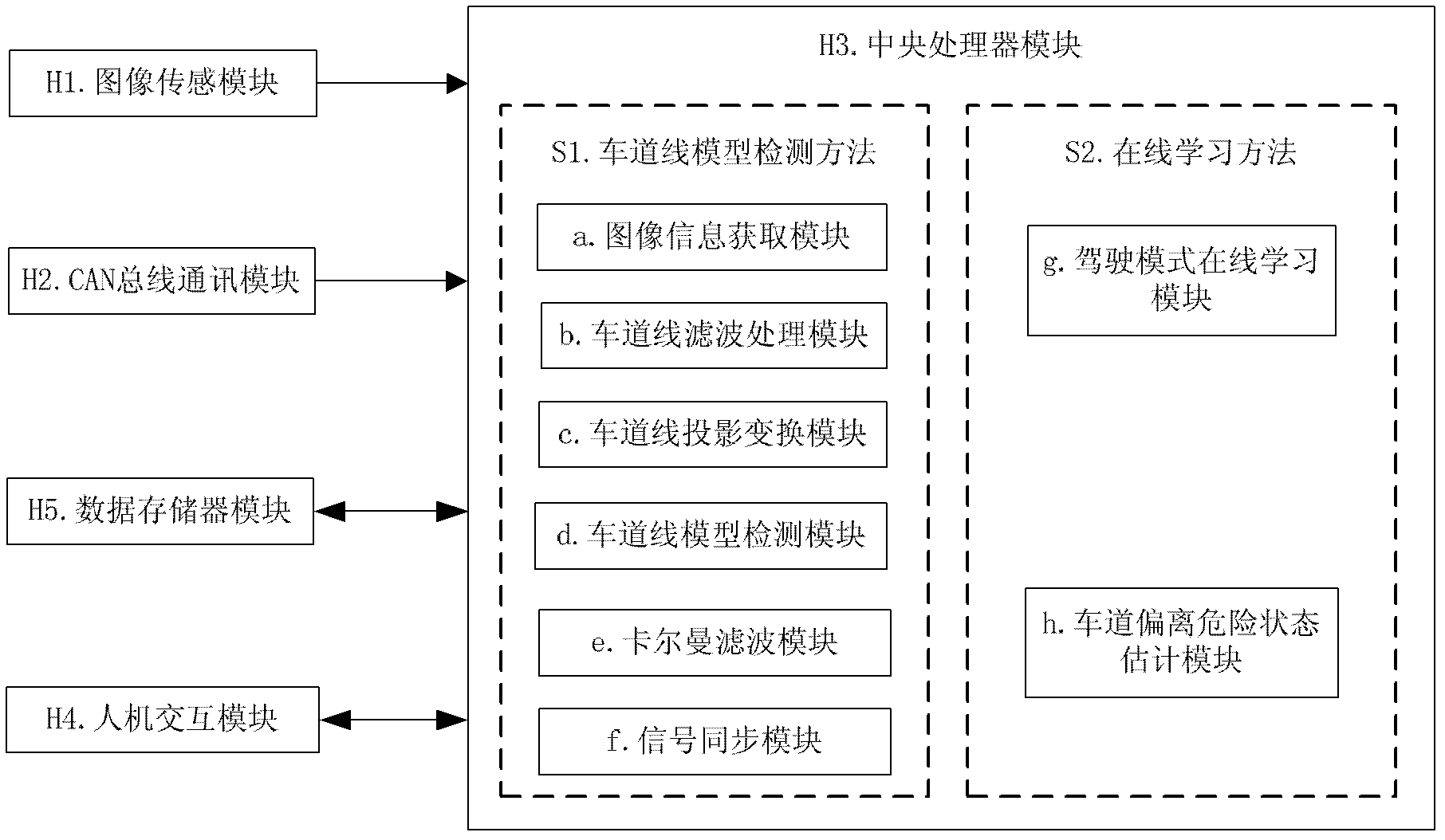
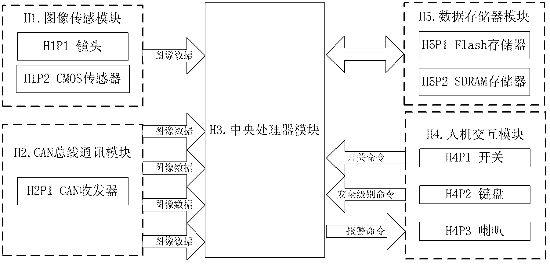
[0037] A lane departure warning system based on a lane line model detection method and an online learning method. The hardware system includes: an image sensing module (H1), which is used to obtain image data in front of the car in real time; a CAN bus communication module (H2), which communicates with the car CAN The bus communicates to obtain vehicle speed signals, turn signal signals, brake signals, and accelerator signals in real time; the central processing unit module (H3) provides a computing platform for the lane line model detection method (S1) and online learning method (S2), man-machine Interactive module (H4), this module includes a switch, two adjustment buttons, LED display and horn, the switch is used to turn on and off the lane departure warning system, the two adjustment buttons are used to set the danger warning level, and the LED display is used to display Th...

Embodiment 2

[0042] Embodiment 2 provides a detailed description of each module of the detection layer:

[0043] A lane departure warning system based on a lane line model detection method and an online learning method. The software system includes: a lane line model detection method (S1), which is used to detect the lane line in front of a car in real time and calculate the relative distance between the lane line and the car. Position; online learning method (S2), through which the state of the car's lane departure is learned online, effectively distinguishing the lane departure state caused by the driver's conscious lane change operation and the lane departure caused by the driver's unconscious driving of the car from the lane state, and through the learning results, the second lane departure state is given an early warning. Among them, this embodiment describes the implementation method of the lane line model detection method (S1).

[0044] Image information acquisition module (a): Thi...

Embodiment 3

[0067] Embodiment 3 provides a detailed description of each module of the decision-making layer:

[0068]The schematic diagram of the decision-making layer (L3) of the present invention's design is as attached Figure 5 As shown, it includes a driving mode online learning module (f) and a lane departure risk state estimation module (g). Wherein, the driving mode online learning module (f) includes a lane departure judging module (FP1) and an online learning module (FP2). The lane departure dangerous state estimation module (g) includes a dangerous level calculation module (GP1) and an alarm decision (GP2).

[0069] Lane Departure Judgment Module (FP1): First, this module uses the internal parameters and external parameters calibrated by the camera to calculate the positional relationship between the lane line and the vehicle in the three-dimensional space coordinate system, such as Figure 8 shown. Then, calculate the lane departure rate according to formula (8):

[0070] ...


PUM


Abstract

The invention discloses a lane departure alarm system based on a lane line model detection method and an on-line study method, which relates to the technical field of intelligent vehicles and can be used for achieving the function of lane departure alarm. The lane departure alarm system aims at being used in automobiles, and can give out early warning signals when an automobile deviates from a lane caused by fatigue or negligence of a driver so as to avoid risk. The lane departure alarm system comprises a hardware system and a software system, wherein the main function of the hardware system is to obtain image data and automobile state information, store sample data of on-line study and provide a calculating platform for a software method, and the software system comprises the lane line model detection method and the on-line study method. The lane departure alarm system can accurately detect positions of a lane line through the lane line model detection method, can lead users to effectively study on-line driving mode of a driver, performs accurate quantized evaluation on danger in driving state, and effectively reduces false alarm rate of the lane departure alarm system when the danger condition is effectively warned early.

Description

Technical field: [0001] The invention relates to the field of intelligent traffic and intelligent vehicle research, in particular to a lane departure warning system. [0002] The present invention can use the image signal collected by the front camera of the vehicle in real time to detect the lane line through the image processing technology, and at the same time, can learn the driver's driving mode through the pattern recognition technology, and can detect the driver's fatigue driving or negligent driving. The vehicle will be alerted when the vehicle deviates from the lane, and the driver will be reminded to correct the vehicle, thereby reducing the occurrence of potential traffic accidents. Background technique: [0003] With the continuous development of economy and transportation, automobiles have become an indispensable means of transportation for people. However, with the continuous improvement of the utilization rate of automobiles, the traffic accident rate has also...

Claims


Application Information

Patent Timeline
Patent Type & Authority Applications(China)
IPC IPC(8): B60W50/14B60W30/12B60W40/06B60W40/09
Inventor 不公告发明人
Owner 周圣砚
Learn More