Rock trenching machine and trenching method

A trough machine, rock technology, applied in the direction of earth mover/shovel, construction, etc., can solve the problems of reservoir water leakage, unable to form a continuous wall, and not fundamentally solve the leakage, etc., to achieve anti-seepage. The effect of high height, strong wall continuity and simple structure

Inactive Publication Date: 2012-08-01
海力控股集团有限公司
View PDF4 Cites 4 Cited by
  • Summary
  • Abstract
  • Description
  • Claims
  • Application Information

AI Technical Summary

Problems solved by technology

[0002] Some mountainous reservoirs are located on rocky geology with serious rock fissures, and the water leakage in the reservoir is serious. At present, the anti-seepage treatment method is high-pressure jet grouting. This construction method cannot form a complete continuous wall and does not fundamentally solve the leakage. question

Method used


Image

  • Rock trenching machine and trenching method
  • Rock trenching machine and trenching method

Examples


Embodiment Construction

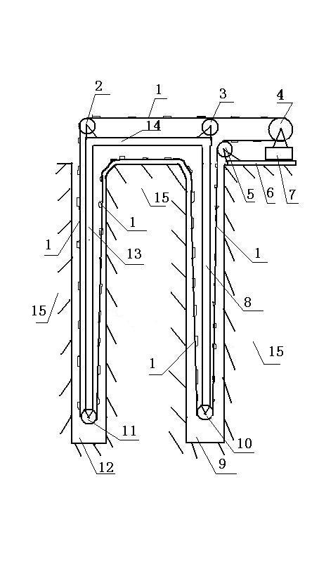
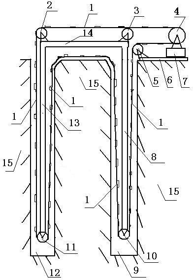
[0011] Accompanying drawing is a kind of concrete embodiment of the present invention, and this embodiment comprises slotting machine track 6 and the dolly 7 on the track, driving wheel 4 is installed on the dolly, cross bar 14 left lower end is provided with upright bar A13, upright bar A The lower end is provided with a rotating wheel E11, the upper end of the vertical rod A is provided with a rotating wheel A2, the lower right end of the cross bar 14 is provided with a vertical rod B8, the lower end of the vertical rod B is provided with a rotating wheel D10, and the upper end of the vertical rod B is provided with a rotating wheel B3. C5 is located at the left end of the track and the upper right end of hole B9; the steel wire 1 starts from the driving wheel, goes around the turning wheel B, turning wheel A, turning wheel E, cuts into the rock 15, enters turning wheel D, and then walks around turning wheel C Enter the driving wheel.

[0012] When the present invention work...


PUM


Abstract

The invention relates to a rock trenching machine and a trenching method for seepage resistance of rock cracks. The rock trenching machine comprises a trenching machine track and a trolley on the track, wherein a driving wheel is arranged on the trolley; a vertical rod A is arranged at the lower left end of a cross bar; a rotating wheel E is arranged at the lower end of the vertical rod A; a rotating wheel A is arranged at the upper end of the vertical rod A; a vertical rod B is arranged at the lower right end of the cross bar; a rotating wheel D is arranged at the lower end of the vertical rod B; a rotating wheel B is arranged at the upper end of the vertical rod B; a rotating wheel C is arranged at the left end of the track and the upper right end of a hole B; and a steel wire starts from the driving wheel, rounds the rotating wheel B, the rotating wheel A and the rotating wheel E, is cut into rocks and then enters the rotating wheel D and finally rounds the rotating wheel C and enters the driving wheel. When the rock trenching machine works, two holes are drilled in a rock to be trenched and then the vertical rod A and the vertical rod B of the trenching machine are implanted into the holes; the steel wire winds around the rotating wheels and the driving wheel; and the driving wheel is driven to drive the steel wire to rotate and cut the rocks to form a trench.

Description

1. Technical field [0001] The invention relates to a groove forming machine and a groove forming method, in particular to a rock groove forming machine and a groove forming method for anti-seepage formation of rock fissures. 2. Background technology: [0002] Some mountainous reservoirs are located on rocky geology with serious rock fissures, and the water leakage in the reservoir is serious. At present, the anti-seepage treatment method is high-pressure jet grouting. This construction method cannot form a complete continuous wall and does not fundamentally solve the leakage. question. 3. Contents of the invention: [0003] The invention makes up for the shortcomings of the above anti-seepage equipment and construction methods, and provides a rock groove forming machine and a groove forming method capable of building an underground continuous wall on the rock. [0004] The present invention is achieved through the following technical solutions: [0005] A rock grooving m...

Claims


Application Information

Patent Timeline
Patent Type & Authority Applications(China)
IPC IPC(8): E02F5/06
Inventor 张永忠
Owner 海力控股集团有限公司
Why Eureka
Try Eureka