Portable air compressor with wire winding function

An air compressor, portable technology, applied in the direction of liquid variable capacity machinery, mechanical equipment, variable capacity pump components, etc., can solve the problems of potential safety hazards, machine damage, leakage, etc., to eliminate potential safety hazards and prolong service life , Eliminate the effect of leakage

Active Publication Date: 2014-06-18
湖南省瑞柯电子科技有限公司
View PDF4 Cites 0 Cited by
  • Summary
  • Abstract
  • Description
  • Claims
  • Application Information

AI Technical Summary

Problems solved by technology

[0003] Because the power cord is long and cannot be put away, it is inconvenient to carry, and most of the wire sheaths of the power cord are made of soft and fragile polymer materials, which are often easily squeezed or cut by sharp objects, resulting in leakage, and there are safety hazard, or cause damage to the machine

Method used


Image

  • Portable air compressor with wire winding function
  • Portable air compressor with wire winding function
  • Portable air compressor with wire winding function

Examples


Embodiment 1

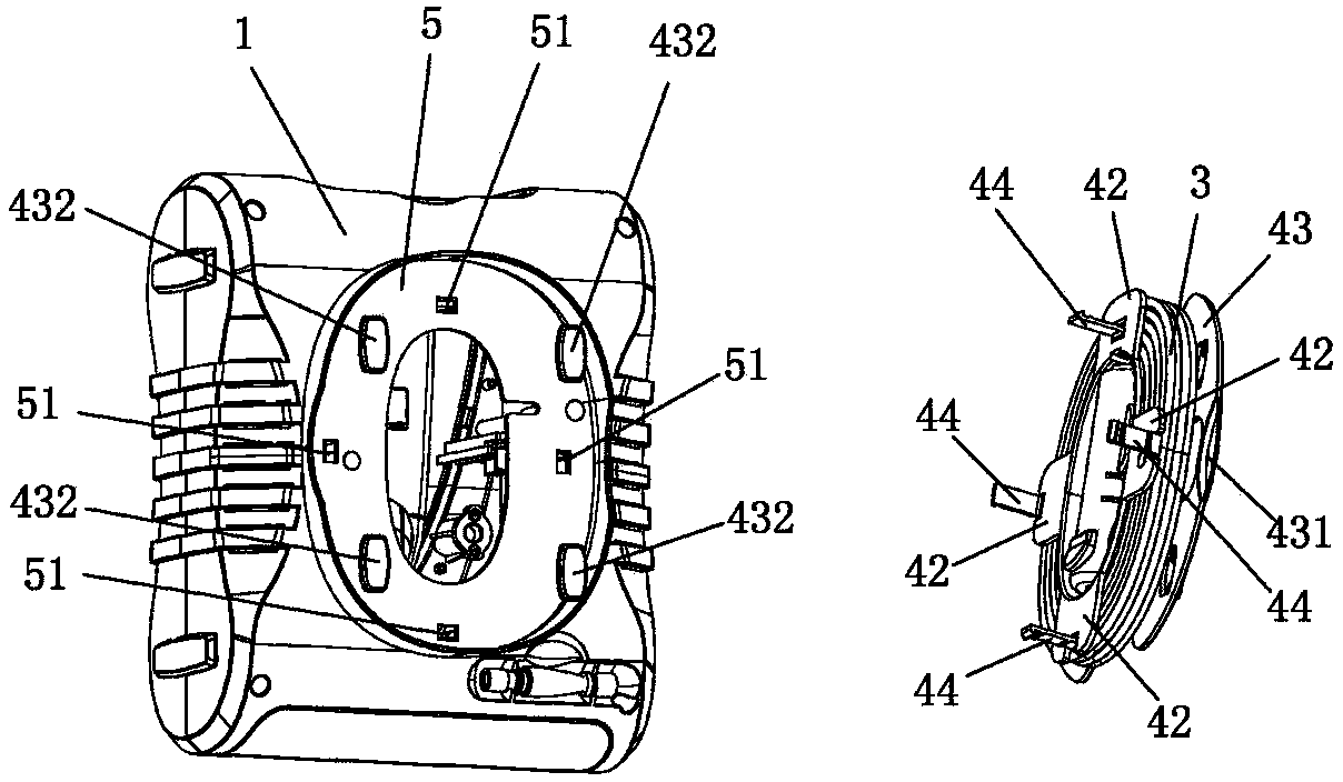
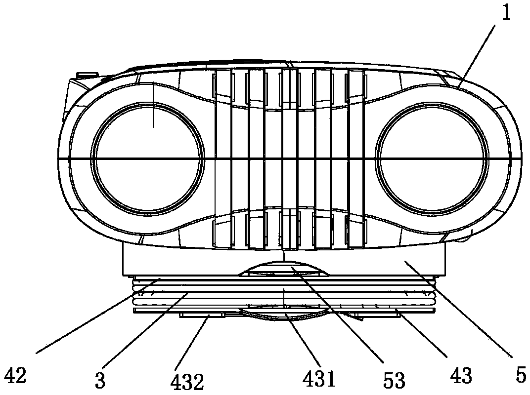
[0058] Embodiment 1 of a portable air compressor with a wire take-up function of the present invention, such as Figure 1 to Figure 5 As shown, it includes: a casing 1, an air compressor core 2, a wire take-up device 4 and a power cord 3; the bottom of the casing 1 is provided with a boss 5, and the boss 5 is provided with a clamping hole 51. The air compressor core 2 is arranged inside the casing 1 .

[0059] like image 3 , Figure 4 , Figure 5 As shown, the arrangement of the boss 5 increases the storage space inside the casing 1 , so that the core components such as the air compressor core 2 are not affected by the wire take-up device 4 .

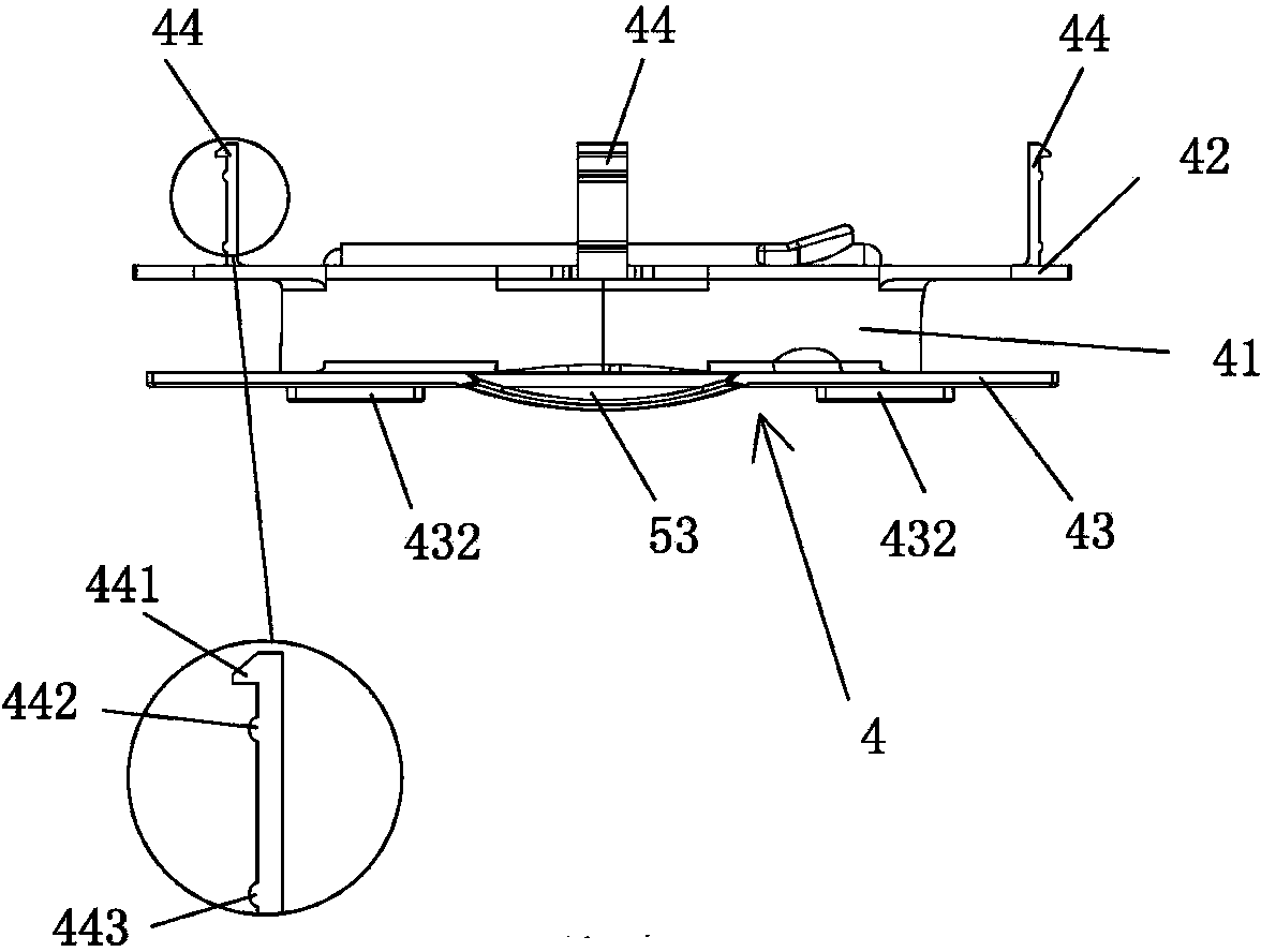
[0060] like figure 1 , image 3 , Figure 5 As shown, the wire take-up device 4 is arranged at the bottom of the boss 5 , the wire take-up device 4 can be pulled out and pushed from the boss 5 through the corresponding cooperation with the clamping hole 51 , and the power cord 3 is wound around the wire take-up device 4 .

[00...

Embodiment 2

[0075] Embodiment 2 of a portable air compressor with a wire take-up function of the present invention, the main technical solution of this embodiment is the same as that of Embodiment 1, and the features not explained in this embodiment are explained in Embodiment 1 , which will not be repeated here. The difference between this embodiment and Embodiment 1 is:

[0076] The number of the clamping feet 44 is set to one, and the clamping feet 44 are fixed to the center of the upper surface of the baffle plate 42 on the winding wire; .

[0077] When one clip 44 is used, the clip 44 can be appropriately set to be slightly thicker to prevent the clip 44 from being broken by excessive force. The structure of one clip 44 matching one clip hole 51 is simpler, material is saved, the mold is easy to manufacture, the cost is lower, and the production efficiency is higher.

[0078] like figure 1 , image 3 , Figure 4 As shown, the edge of the boss 5 is provided with a first recess ...

Embodiment 3

[0081] Embodiment 3 of a portable air compressor with a wire take-up function of the present invention, the main technical solution of this embodiment is the same as that of Embodiment 2, and the features not explained in this embodiment are explained in Embodiment 2 , which will not be repeated here. The difference between this embodiment and the second embodiment is that the number of the clamping feet 44 is set to two, and the two clamping feet 44 are arranged oppositely;


PUM


Abstract

The invention relates to the technical field of portable air compressors, in particular to a portable air compressor with a wire winding function, which comprises a shell, an air compressor mechanism, a wire winding device and a power wire. A boss is arranged at a bottom of the shell, clamping holes are arranged on the boss, the air compressor mechanism is arranged inside the outer shell, and the wire winding device is arranged at the bottom of the boss. The wire winding device is pulled out from the boss or pushed into the boss by correspondingly matching with the clamping holes. The power wire is wound on the wire winding device. By the aid of the wire winding device additionally arranged on the portable air compressor, the power wire can be wound neatly and can be used and carried conveniently, the service life of the portable air compressor is prolonged, and the integral appearance and structure of the portable air compressor are attractive. Meanwhile, the power wire can be protected well without being squeezed or scratched, the potential safety hazard of an electricity leakage in use can be eliminated, portability is practically realized, and the service life of the portable air compressor is prolonged.

Description

technical field [0001] The invention relates to the technical field of portable air compressors, in particular to a portable air compressor with a wire take-up function. Background technique [0002] The portable air compressor is a kind of electrical equipment, so a long power cord and plug need to be provided. The structure of the portable air compressor in the prior art includes a shell, a power cord, and a plug fixed in the shell. The core of the air compressor, an air pressure gauge, and the air pressure gauge are installed on the upper end of the shell, and the air pressure gauge and the shell adopt a clamping structure of protrusions and grooves. [0003] Because the power cord is long and cannot be put away, it is inconvenient to carry, and most of the wire sheaths of the power cord are made of soft and fragile polymer materials, which are often easily squeezed or cut by sharp objects, resulting in leakage, and there are safety hazard, or cause damage to the machine...

Claims


Application Information

Patent Timeline
Patent Type & Authority Patents(China)
IPC IPC(8): F04B39/00B65H75/36
Inventor 杨琪张春
Owner 湖南省瑞柯电子科技有限公司
Why Eureka
Try Eureka