Method and device for measuring pixel pitch of image sensor based on point-target image splicing technology

An image sensor, pixel pitch technology, applied in measurement devices, optical devices, instruments, etc., can solve problems such as defocusing, and achieve the effects of improving repeatability, reducing errors, and amortizing errors

Active Publication Date: 2012-08-01
HARBIN INST OF TECH
8 Cites 8 Cited by

AI-Extracted Technical Summary

Problems solved by technology

[0041] The present invention aims at the problem that the above-mentioned existing measurement method is not suitable for measurement in a small field of view, and the problem that the existing measurement device has defocus, and propose...

Abstract

A method and a device for measuring the pixel pitch of an image sensor based on the point-target image splicing technology, which belong to the length, width or thickness metering field included in the field of metering equipment which is characterized by using an optical method. The method includes placing the point targets in different fields of view, and performing twice imaging of the point targets; constructing linear images according to the two point-target images; searching value ranges of the pixel pitch in the frequency domain, and calculating to obtain the pixel pitch by means of the search algorithm according to the best contact ratio of the actual modulation transfer function(MTF) curve related to the pixel pitch and the theoretical MTF curve related to the pixel pitch under the condition of the least square. Sliders bearing the point targets are arranged on a first guide rail and a second guide rail, and the movement of the slider on the first guide rail matches with the movement of the slider on the second guide rail so that the point targets can be focused correctly to form images on the surface of the image sensor at the position of any field of view. The method and the device for measuring the pixel pitch of the image sensor are favorable for reducing errors among results of single measurements, so that repetition of measuring results can be increased.

Application Domain

Technology Topic

Image

  • Method and device for measuring pixel pitch of image sensor based on point-target image splicing technology
  • Method and device for measuring pixel pitch of image sensor based on point-target image splicing technology
  • Method and device for measuring pixel pitch of image sensor based on point-target image splicing technology

Examples

  • Experimental program(1)

Example Embodiment

[0067] The specific embodiments of the present invention will be described in further detail below in conjunction with the accompanying drawings.
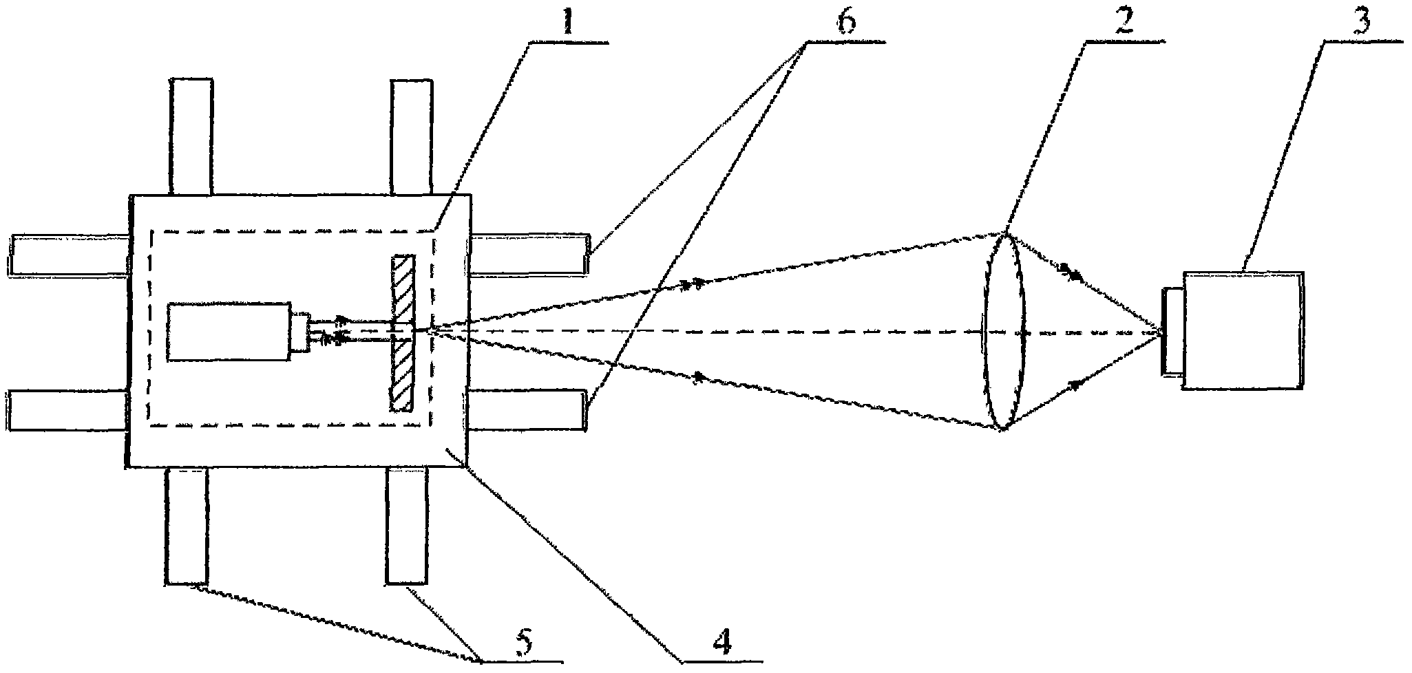
[0068] figure 1 A schematic diagram of the structure of an image sensor pixel pitch measuring device using point target images; the device includes a point target 1, an optical system 2, an image sensor 3, a slider 4, and a first guide rail 5 perpendicular to the optical axis. 1 The image is imaged onto the surface of the image sensor 3 through the optical system 2; and, the device also includes a second guide rail 6 along the optical axis. The slider 4 carrying the point target 1 is installed on the first guide rail 5 and the second guide rail 6, sliding The movement of the block 4 on the first guide rail 5 is matched with the movement of the slider 4 on the second guide rail 6, so that the point target 1 is in-focus imaged onto the surface of the image sensor 3 at any field of view position; among them, the point target 1 is For a pinhole with a diameter of 15 μm, the lateral magnification of the optical system 2 is 0.0557.
[0069] Image sensor pixel pitch measurement method using point and target image stitching, the flowchart is as figure 2 As shown, the method steps are as follows:
[0070] a. The image sensor 3 images the static point target 1 for the first time, obtains the first frame of the initial static point target image, and extracts the pixel coordinate position of the point target image (x 1 , Y 1 );
[0071] b. Make the point target 1 move along the 3 rows of the image sensor with a displacement of h = 1.526mm, and then keep the point target 1 in a static state;
[0072] c. Keep the exposure time of the image sensor 3 unchanged, the image sensor 3 images the static point target 1 for the second time to obtain the second frame of the initial static point target image, and extract the pixel coordinate position of the point target image (x 2 , Y 2 );
[0073] d. Remove the point target 1 and keep the exposure time of the image sensor 3 unchanged. The image sensor 3 images the background to obtain the interference image, and the maximum gray value in the interference image is used as the threshold, which is 10;
[0074] e. The first frame of the initial static point target image obtained in step a, the gray value of the pixel whose gray value is less than the threshold obtained in step d is corrected to 0, and the first frame of corrected static point target image is obtained; step c is obtained The second frame of the initial static point target image of, the gray value of the pixel whose gray value is less than the threshold value obtained in step d is corrected to 0, and the second frame of corrected static point target image is obtained;
[0075] f. The first frame of corrected static point target image and the second frame of corrected static point target image obtained in step e are superimposed, and the gray values ​​of all pixels in the rows of the two point target images in the superimposed new image are added together And divide by 2 to get the new gray value; and the pixel coordinate position obtained in step a (x 1 , Y 1 ) And the pixel coordinate position obtained in step c (x 2 , Y 2 ) The gray value of the pixel covered by the connection is replaced with the new gray value to obtain the structure point expansion function image;
[0076] g. The structure point spread function image obtained in step f, extract the entire line of information of the line where the linear light spot is located, as a structure line spread function image, the structure line spread function image has n=1280 elements;
[0077] h. Carry out discrete Fourier transform and take the modulus of the structure line extension function image obtained in step g at a distance of 1 to obtain the initial modulation transfer function image, which has the same structure line extension obtained in step g The number of the same elements of the function image is n, that is, n discrete spectral components, which are respectively M according to the order of spatial frequency from small to large 0 , M 1 , M 2 ,..., M n-1 , Under this sequence, the modulation transfer function value corresponding to the initial modulation transfer function value reaching the minimum value for the first time is M i , Its subscript number is i;
[0078] i. According to the displacement h in step b, calculate the distance between the two point target images after the optical system 2 with the lateral magnification ratio β is: d=h·β=1.526×0.0557=0.085mm;
[0079] j. According to the distance d between the two point target images obtained in step i and the modulation transfer function model MTF(f)=|sinc(πfd)| corresponding to the construction line spread function obtained in step g, the g th The cut-off frequency of the image frequency spectrum of the step construction line spread function is: f = 1 d = 1 h · β = 1 0.085 = 11.7647 lp / mm ;
[0080] k. According to the cut-off frequency f of the image spectrum of the construction line spread function obtained in step j and the modulation transfer function value obtained in step h is M i-1 And M i+1 The corresponding spatial frequency values ​​are respectively equal, namely: f=(i-1)/(nl min ) And f=(i+1)/(nl max ), the pixel pitch range of the image sensor 3 is obtained as: l min =(i-1)/(nf)=(i-1)d/n=(i-1)hβ/n and l max =(i+1)/(nf)=(i+1)d/n=(i+1)hβ/n;
[0081] l. According to the pixel pitch value range obtained in step k, the pixel pitch is divided into N parts, respectively, l 1 , L 2 ,..., l N , Where l 1 = L min , L N = L max;
[0082] m. According to the order of spatial frequency from small to large, draw the n modulation transfer function values ​​obtained in step h into a curve, and select this curve from M 0 From the beginning to the first maximum value, and excluding all the modulation transfer function values ​​of the first minimum value, a total of K are used as comparison data, and the K modulation transfer function values ​​are respectively M K1 , M K2 ,..., M KK , Substitute the N pixel pitches obtained in step 1 into the following formulas: Among the N values ​​obtained by the formula, the pixel pitch l corresponding to the minimum value is the desired value.
[0083] According to the above ideas, the pixel pitch was measured 100 times, and the measurement results obtained are listed in the following table:
[0084]
[0085] In the above-mentioned image sensor pixel pitch measurement method using point and target image stitching, the e and f steps are replaced by:
[0086] e'. The first frame of initial static point target image obtained in step a and the second frame of initial static point target image obtained in step c are superimposed, and the gray value of the superimposed image is less than the threshold value obtained in step d2 The gray value of the pixel that is doubled is corrected to 0, and the corrected superimposed image is obtained;
[0087] f'. Add the gray values ​​of all pixels in the row of the two point target images in the corrected superimposed image obtained in step e'and divide by 2 to obtain the new gray value; and the pixel coordinate position obtained in step a (x 1 , Y 1 ) And the pixel coordinate position obtained in step c (x 2 , Y 2 ) The gray value of the pixel covered by the connection is replaced with the new gray value to obtain the structure point spread function image.

PUM

no PUM

Description & Claims & Application Information

We can also present the details of the Description, Claims and Application information to help users get a comprehensive understanding of the technical details of the patent, such as background art, summary of invention, brief description of drawings, description of embodiments, and other original content. On the other hand, users can also determine the specific scope of protection of the technology through the list of claims; as well as understand the changes in the life cycle of the technology with the presentation of the patent timeline. Login to view more.

Similar technology patents

Classification and recommendation of technical efficacy words

  • Amortized error
  • Reduce mistakes

Terminal positioning track fitting method based on Bezier curve

ActiveCN102998684AReduce mistakesSatellite radio beaconingSatellite navigationFitting methods
Owner:XIAMEN YAXON NETWORKS CO LTD

Multifunctional road soil roadbed freezing and thawing circulating test device

ActiveCN101923085ASolving Elasticity ProblemsReduce mistakesRoadwaysEarth material testingTest measurementFrost
Owner:CCCC SECOND HIGHWAY CONSULTANTS CO LTD
Why Eureka
Try Eureka