Steel rail corrugation laser measuring device

A laser measurement and wave-shaped technology, applied in the direction of measuring devices, optical devices, instruments, etc., can solve the problems of shortening the service life of related parts of the track and rolling stock, increasing the force of the wheel and rail, and affecting the health of residents, etc., to achieve measurement The data is accurate and reliable, the step size is constant, and the detection is convenient and fast.

Inactive Publication Date: 2012-08-01
SOUTHWEST JIAOTONG UNIV
View PDF4 Cites 15 Cited by
  • Summary
  • Abstract
  • Description
  • Claims
  • Application Information

AI Technical Summary

Problems solved by technology

[0004] The wavy wear of the rail makes the surface of the rail head uneven to varying degrees, causing a sharp increase in the force of the wheel and rail, causing the rolling stock and various components of the track to bear excessive dynamic loads, thus significantly shortening the track and rolling stock related components. service life
In addition, due to vibration, the wavy worn rails will cause noise, cause environmental pollution, and seriously affect the health of residents on both sides of urban rail transit and high-speed lines

Method used


Image

  • Steel rail corrugation laser measuring device
  • Steel rail corrugation laser measuring device
  • Steel rail corrugation laser measuring device

Examples


specific Embodiment approach

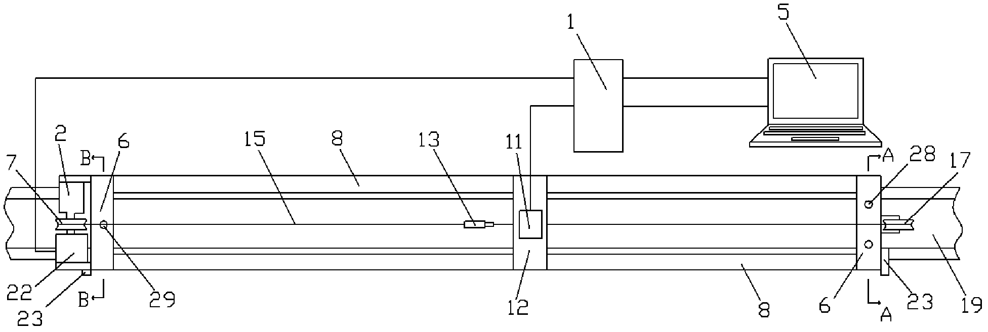
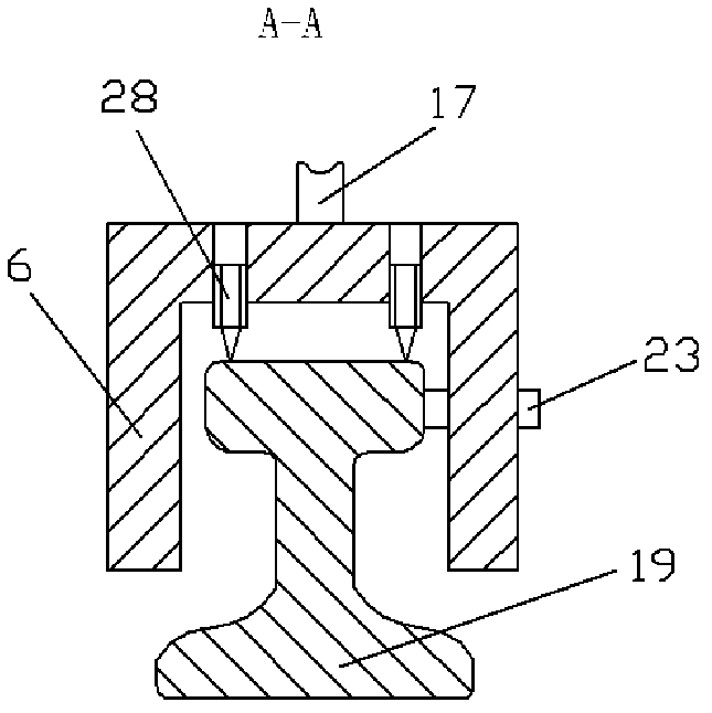
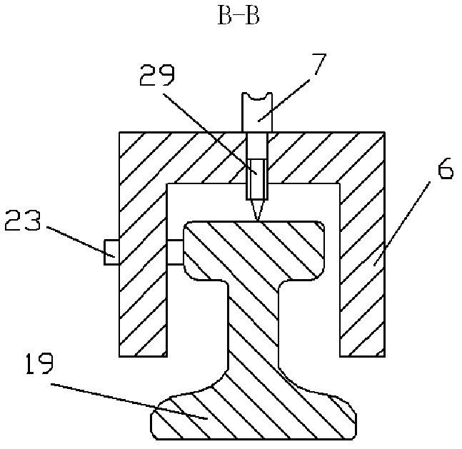
[0028] Figure 1-3 As shown, a specific embodiment of the present invention is: a rail wave wear laser measuring device, which is composed of:

[0029] Both ends of the device have a bracket 6 that can be placed on the rail 19. Guide rails 8 are fixed on both sides of the top of the bracket 6, and a slider 12 is fitted on the guide rail 8; the laser head 11 of the laser displacement sensor 1 is fixed on the slider 12. Above, the serial port and the USB interface of the laser displacement sensor 1 are connected to the serial port and the USB interface of the computer 5 respectively;

[0030] Motor 2 is fixed on the bracket 6 at one end, fixed pulley 1 7 is connected on the shaft of motor 2, fixed pulley 2 17 is installed on the bracket 6 of the other end; Pass fixed pulley 1 7, fixed pulley 2 17 and then be connected with slide block 12; The shaft end of motor 2 is connected with incremental photoelectric encoder 22, the signal output end of this incremental photoelectric enco...


PUM


Abstract

The invention relates to a steel rail corrugation laser measuring device. The steel rail corrugation laser measuring device has a structure that: both ends of the device are provided with a bracket which can be arranged on a steel rail respectively; both sides of the top of each bracket are fixedly provided with guide rails; a sliding block is sleeved on the guide rails; the laser head of a laser displacement sensor is fixed to the sliding block; the serial port and the universal serial bus (USB) interface of the laser displacement sensor are connected with the serial port and the USB interface of a computer respectively; the bracket on one end is fixedly provided with a motor; the shaft of the motor is connected with a fixed pulley 1; the bracket on the other end is provided with a fixed pulley 2; one end of a steel wire is connected with the sliding block, and the other end of the steel wire rounds the fixed pulley 1 and the fixed pulley 2 and then is connected with the sliding block; the shaft end of the motor is connected with an incremental photoelectric encoder; and the signal output end of the incremental photoelectric encoder is connected with the control signal input end of the laser displacement sensor. The measuring device can conveniently measure the condition of corrugation on the surface of the steel rail in the site and has the advantages of high automation degree, convenience for operation, high measurement accuracy and high reproducibility of test data.

Description

technical field [0001] The invention relates to a detection device for railway rails. Background technique [0002] After the rail is put into use, as the operation time increases, a regular irregularity similar to a wave shape will gradually appear in some parts of the top of the rail along the longitudinal direction. We call this phenomenon the wavy wear of the rail. . [0003] In recent years, as my country's railways continue to develop towards heavy loads and high speeds, the impact of wavy wear has become more and more serious, making it an urgent problem to be solved by the railway department. Wavy wear not only occurs on railway rails, but also exists on all track-based operating lines, including subways, trams and various track lines, so solving the problem of wavy wear is very important for real life Many aspects are very important. [0004] The wavy wear of the rail makes the surface of the rail head uneven to varying degrees, causing a sharp increase in the fo...

Claims


Application Information

Patent Timeline
Patent Type & Authority Applications(China)
IPC IPC(8): G01B11/30
Inventor 王文健刘启跃王衡禹杜星金学松朱旻昊
Owner SOUTHWEST JIAOTONG UNIV
Why Eureka
Try Eureka