
Dynamic balance testing method for rotatable part
A technology of rotating parts and testing methods, which is applied in the field of mechanics, can solve problems such as inconsistencies in states, and achieve the effects of improving accuracy, improving measurement accuracy, improving measurement accuracy and trimming efficiency
Patent Information
- Authority / Receiving Office
- CN · China
- Patent Type
- Applications(China)
- Current Assignee / Owner
- Publication Date
- 2012-08-01
Smart Images
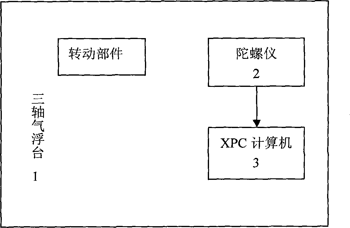
Figure 1 
Figure 2 
Figure 3
Abstract
Description
technical field
[0001] The invention relates to the field of mechanics, in particular to a method for testing the dynamic balance of rotating components. Background technique
[0002] The microwave imager used on the satellite works in a mechanical scanning mode. The weight of the rotating part is 60kg, and the rotation period is divided into two levels: 1.7s and 2s. When the large-scale high-speed rotating parts represented by the microwave imager are running, the disturbance torque generated by the dynamic unbalance exceeds the control bandwidth of the attitude-orbit control subsystem, and it cannot be effectively controlled, which will cause great interference to the attitude. It will also cause coupling of other flexible parts, causing the satellite to not work properly. Therefore, before installing the star, the interference torque of the large rotating parts should be measured, and the static unbalance and dynamic unbalance should be trimmed to reduce the interference...
Examples
Embodiment Construction
[0027] Preferred embodiments of the present invention will be described below in conjunction with the accompanying drawings.
[0028] Before describing the method of the present invention, the test device to be used in the present invention will be described first.
[0029] Such as figure 1 As shown, the testing device to be used in the present invention includes a three-axis air bearing table 1 , a gyroscope 2 and an XPC computer 3 . Wherein, the three-axis air bearing platform 1 selects a spherical air bearing to support the simulated platform body to realize microgravity within a certain angle range and the simulation of the free rotation environment in the directions of X, Y, and Z axes; the gyroscope Installed on the three-axis air bearing platform 1, it is used to measure the rotational angular velocity of the three-axis air bearing platform; the XPC computer 3 collects the angular velocity signal measured by the gyroscope 2 in real time, and eliminates the measurement ...