
Manufacturing device of integrated optical fiber laser collimator

A production device, fiber laser technology, applied in the direction of optics, instruments, optical components, etc., can solve the problems of installation and adjustment errors, detection and manufacturing asynchronous, easy to damage the end face of the optical fiber, etc., to reduce the scrap rate, reduce the loss of light energy and Good damage threshold and collimation effect

Inactive Publication Date: 2014-06-18
UNIV OF SCI & TECH OF CHINA
View PDF4 Cites 0 Cited by
  • Summary
  • Abstract
  • Description
  • Claims
  • Application Information

AI Technical Summary

Problems solved by technology

[0004] In order to solve the problems of installation and adjustment errors in fiber laser alignment technology, adhesives and air gaps that easily damage fiber end faces, and detection and manufacturing asynchronous problems

Method used


Image

  • Manufacturing device of integrated optical fiber laser collimator
  • Manufacturing device of integrated optical fiber laser collimator
  • Manufacturing device of integrated optical fiber laser collimator

Examples


Embodiment

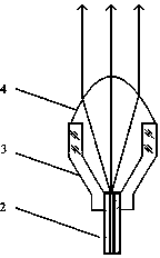
[0019] see figure 1 , the integrated fiber laser collimator includes a laser 1 and an optical fiber 2, one end of the optical fiber 2 is connected to the laser 1, the other end of the optical fiber 2 is connected to a bucket-shaped sleeve 3, and the end of the optical fiber 2 extends into the sleeve 3, The bucket-shaped casing has a maximum inner diameter of 5mm. The sleeve 3 is provided with a droplet lens 4 , the bottom of which is connected to the optical fiber 2 , and the top of the droplet lens 4 is curved and located outside the sleeve 3 .

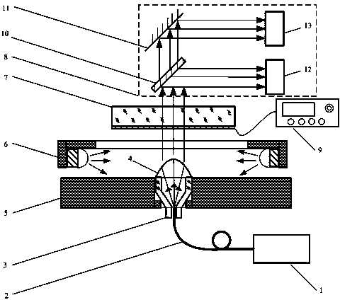
[0020] see figure 2 , The device of the integrated fiber laser collimator includes a transparent conductive glass upper electrode 7, a lower electrode 5, a high voltage AC and DC power supply 9, a curing mechanism and a beam divergence angle detection device 8. The middle part of the lower electrode 5 is provided with a through hole, and a positioning convex ring is installed in the lower port of the through hole; the curing mecha...


PUM


Abstract

The invention relates to a manufacturing device of an integrated optical fiber laser collimator. The manufacturing device of the integrated optical fiber laser collimator comprises a transparent or netlike upper electrode, a lower electrode, a high-frequency alternating current-direct current power supply, a curing mechanism and a light beam diffusion angle detection device, wherein the middle part of the lower electrode is provided with a through hole and the lower port of the through hole is internally provided with a positioning convex ring; the curing mechanism is provided with an annular ultraviolet light source and is located between the upper electrode and the lower electrode; and the light beam diffusion angle detection device is located above the upper electrode. The collimator disclosed by the invention has a good collimation effect, and can be used for greatly reducing the optical energy loss of the end face and improving the energy transmission threshold value; the device disclosed by the invention combines steps of regulating surface shape of a liquid drop by an electric field, curing a liquid drop by a micro lens and detecting the lens surface shape and the collimation effect in real time, so as to detect the collimated light beam diffusion angle in real time, guarantee the synchronization of manufacturing and detecting, and reduce the rejection ratio.

Description

technical field [0001] The invention belongs to the technical field of laser optical fibers, and in particular relates to a manufacturing device of an integrated optical fiber laser collimator. Background technique [0002] In the existing laser fiber collimator, the method of gluing the collimating lens and the end face of the fiber is usually adopted, and the prepared self-focusing lens, aspheric lens, spherical lens or lens group is glued on the end face of the fiber. The collimator produced by the method has the following problems: 1. There are installation and adjustment errors, which affect the collimation effect; 2. The adhesive in the optical path is easily damaged in high-power lasers; 3. The detection and production are not synchronized, and it is difficult to control the collimator Precision, high reject rate. In order to improve the performance of the collimator, a lot of research work has been done. For example, the Chinese patent "New Optical Fiber Collimator...

Claims


Application Information

Patent Timeline
Patent Type & Authority Patents(China)
IPC IPC(8): G02B27/30G02B3/12
Inventor 吴朔王克逸曹兆楼郝鹏雷张源
Owner UNIV OF SCI & TECH OF CHINA
Learn More