Device and method for heating and heat preserving of optical devices

A technology of heating and heat preservation, optical devices, applied in the field of optoelectronics, can solve problems such as poor performance of optical devices, and achieve the effects of improving efficiency, reducing power consumption, and wide temperature control range

Active Publication Date: 2012-08-01
BEIJING CHANGCHENG INST OF METROLOGY & MEASUREMENT AVIATION IND CORP OF CHINA
View PDF5 Cites 1 Cited by
  • Summary
  • Abstract
  • Description
  • Claims
  • Application Information

AI Technical Summary

Problems solved by technology

[0005] The purpose of the present invention is to solve the problem of poor working performance of optical devices under the condition of lower than -20°C, and propose a heating and heat preservation device and method for optical devices

Method used


Image

  • Device and method for heating and heat preserving of optical devices
  • Device and method for heating and heat preserving of optical devices
  • Device and method for heating and heat preserving of optical devices

Examples


Embodiment 1

[0036] In this embodiment, the method and device of the present invention will be used to automatically control the heating and heat preservation of the FP filter.

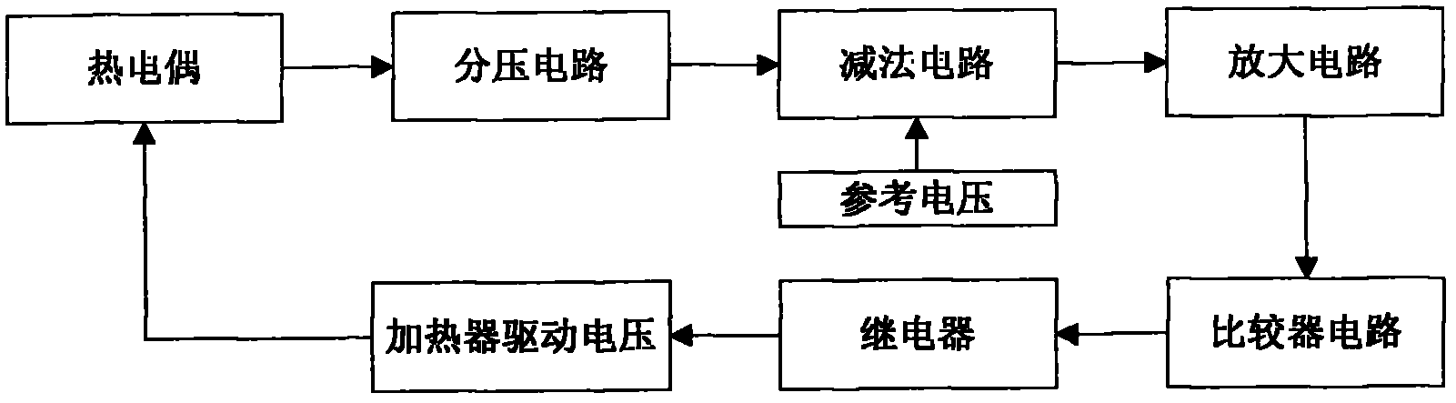
[0037] like figure 1 , the optical device heating and heat preservation device includes a heater 2, a heat insulation layer 3, a waterproof coating 4, a cavity shell 5, a control circuit 6, a thermocouple 7, a heater lead 8, and a thermocouple lead 9.

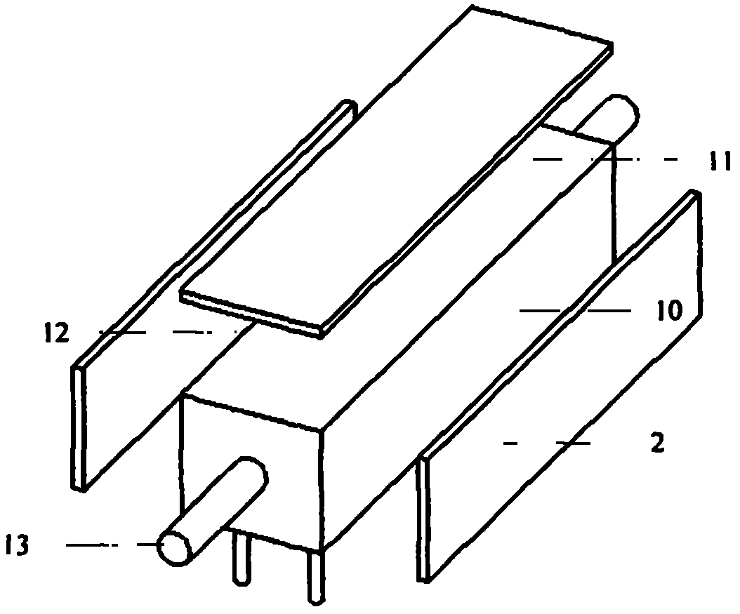
[0038] like image 3 , Figure 4 As shown, the controlled optical device 1 is an FP filter, which is a cuboid device, and the bottom surface 15 of the FP filter has FP filter welding legs 14, and the FP filter leads 13 enter and exit from the left and right sides of the controlled optical device 1. Therefore, the There are optical fiber inlet and outlet holes on the left and right sides of the cavity shell 5 of the heating and insulating device, and welding leg holes are arranged on the bottom surface.

[0039] The connection relationship of the heating and heat...

Embodiment 2

[0052] In this embodiment, the method and device of the present invention will be used to automatically control the heating and heat preservation of the optical fiber etalon.

[0053] like figure 1 , the optical device heating and heat preservation device includes a heater 2, a heat insulation layer 3, a waterproof coating 4, a cavity shell 5, a control circuit 6, a thermocouple 7, a heater lead 8, and a thermocouple lead 9.

[0054] like Figure 5 , Image 6 As shown, the controlled optical device 1 is a fiber optic etalon, which is a cuboid device, and the fiber optic etalon leads 17 enter and exit from the left and right sides of the controlled optical device 1. Therefore, there are optical fibers entering and leaving the left and right sides of the cavity shell 5 of the heating and heat preservation device. hole.

[0055] The connection relationship of the heating and heat preservation device used for the optical fiber etalon is as follows:

[0056] The heater 2 is pas...


PUM


Abstract

The invention relates to a device and a method for heating and heat preserving of optical devices, in particular to a device and a method for temperature control of optical devices in operation at low temperature, which belong to the photoelectronic technical field. The device for heating and heat preserving of optical devices comprises a heater, a heat insulation layer, a waterproof coating, a cavity shell, a control circuit, a thermocouple, a heater lead and a thermocouple lead. Low-temperature heating of optical devices is controlled by the device and the method to enable the devices to operate normally in the low-temperature environment, and the problem that the optical devices cannot be used normally in severe environments is solved. Heating and heat preserving of the optical devices are automatically controlled by means of the control circuit to enable the optical devices to operate normally in a wide temperature range, and the device and the circuit have the advantage of wide temperature control range. The heat insulation layer I used for temperature isolation of the controlled optical device from an external environment, the waterproof coating is arranged outside the heat insulation layer and used for closing, and the cavity shell is used for packaging integrally, so that heating and heat preserving efficiency can be improved, and power consumption in heating and heat preserving is reduced.

Description

technical field [0001] The invention relates to an optical device heating and heat preservation device and method, in particular to a temperature control device and method for optical devices working under low temperature conditions, and belongs to the field of optoelectronic technology. Background technique [0002] Optical devices are used to realize optical signal connection, energy splitting / combining, wavelength multiplexing / demultiplexing, optical path conversion, energy attenuation, directional barrier, optical-electrical-optical conversion, optical signal amplification, optical signal modulation, etc. The general term for functional components. Due to its electrical insulation, anti-electromagnetic interference and other characteristics, optical devices have been widely used in the fields of optical fiber sensing and measurement and optical fiber communication in recent years. [0003] At present, most optical devices are affected by their working principles and int...

Claims


Application Information

Patent Timeline
Patent Type & Authority Applications(China)
IPC IPC(8): G05D23/22
Inventor 张磊胡春艳高超江琴
Owner BEIJING CHANGCHENG INST OF METROLOGY & MEASUREMENT AVIATION IND CORP OF CHINA
Why Eureka
Try Eureka