Cooling structure for motor winding end part

A cooling structure and technology of motor windings, applied in the shape/style/structure of winding conductors, can solve the problems of low direct cooling efficiency at the end of motor windings, achieve improved heat dissipation, easy implementation, and lower operating temperature

Inactive Publication Date: 2012-08-01
INST OF ELECTRICAL ENG CHINESE ACAD OF SCI
View PDF14 Cites 15 Cited by
  • Summary
  • Abstract
  • Description
  • Claims
  • Application Information

AI Technical Summary

Problems solved by technology

[0010] In order to solve the problem of low direct cooling efficiency at the end of the motor winding in the prior art, the present invention proposes a cooling structure at the end of the motor stator winding

Method used


Image

  • Cooling structure for motor winding end part
  • Cooling structure for motor winding end part
  • Cooling structure for motor winding end part

Examples


Embodiment Construction

[0024] The present invention will be further described below in conjunction with the accompanying drawings and specific embodiments.

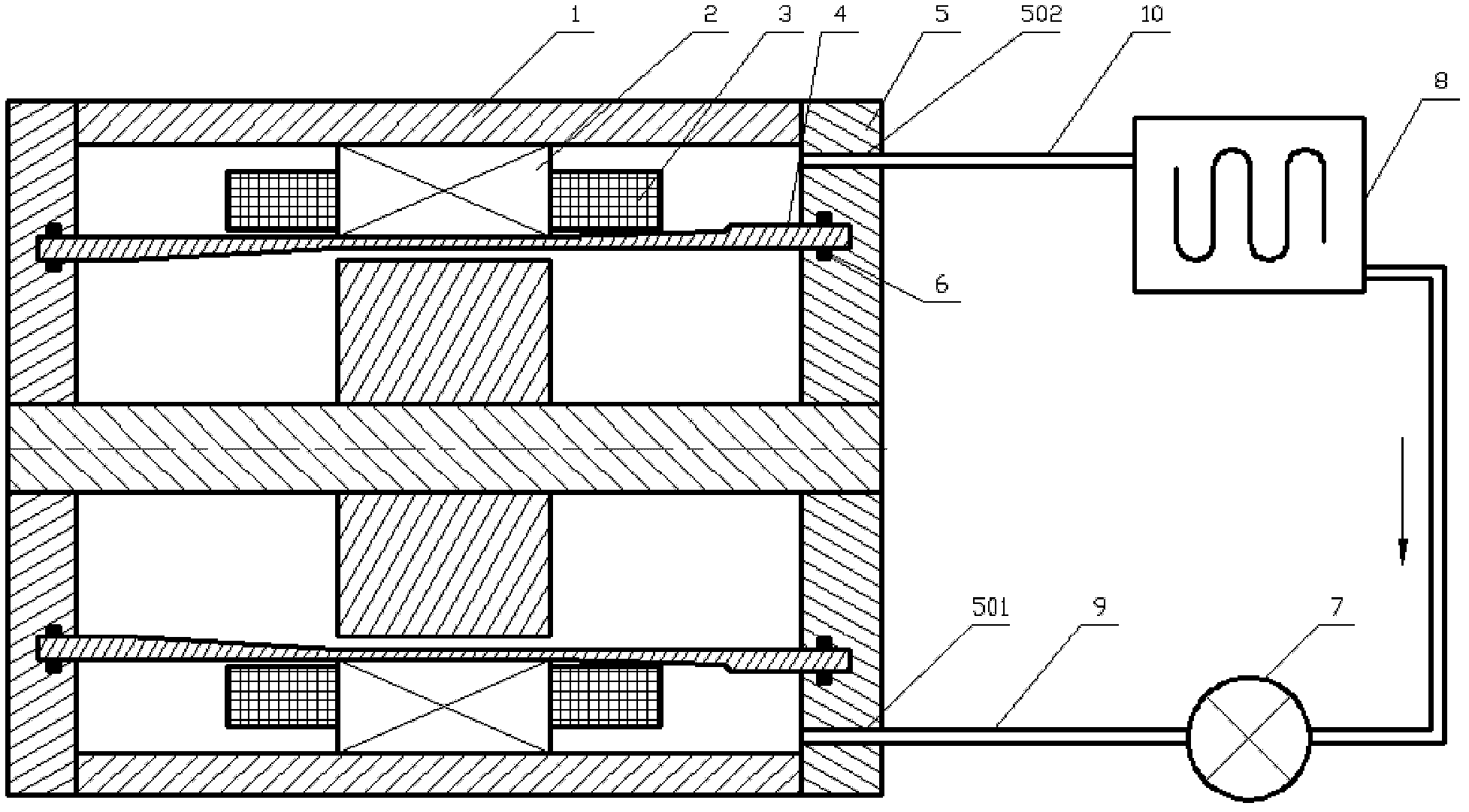
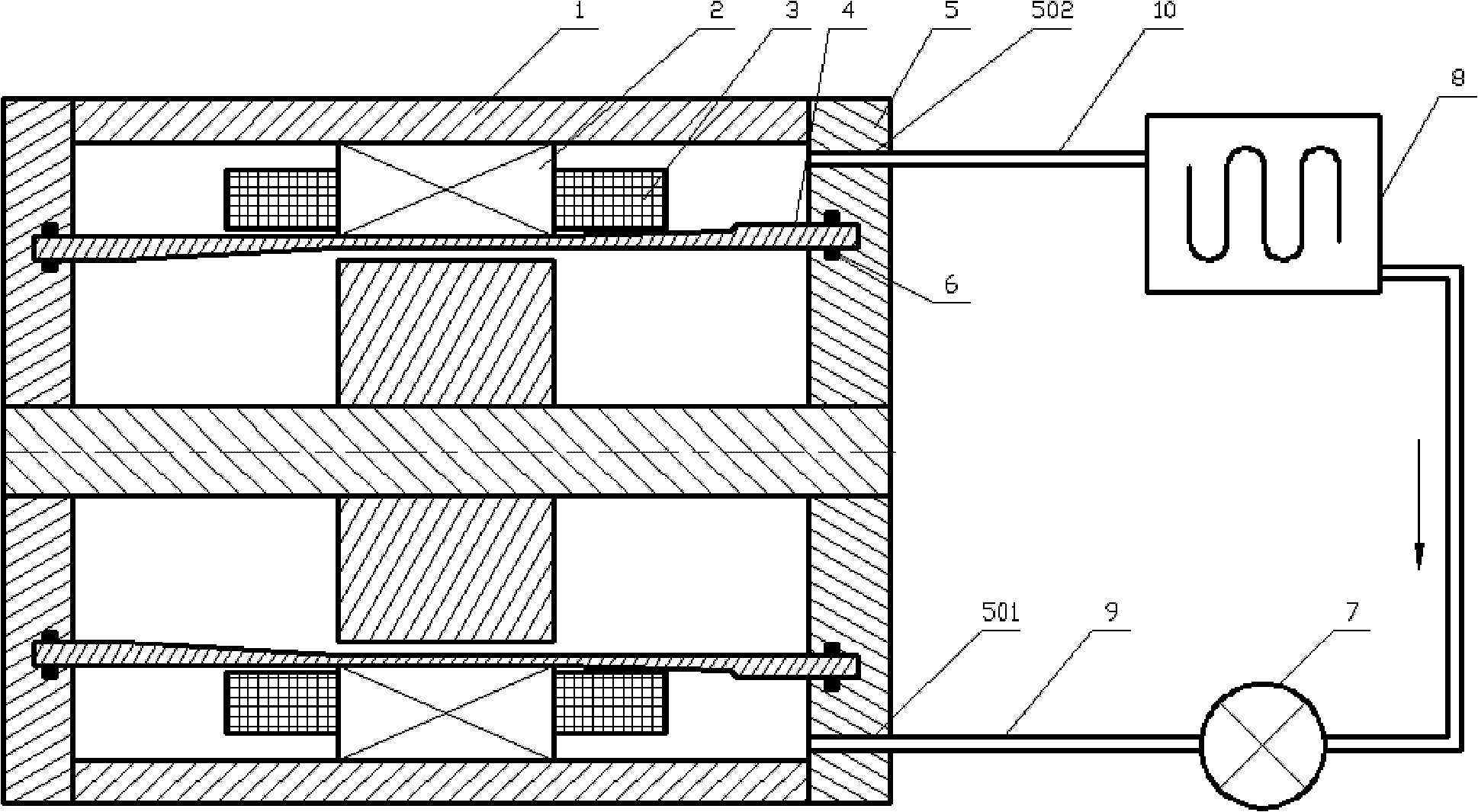
[0025] Such as figure 1 As shown, the motor end cooling structure proposed by the present invention includes: motor housing 1 , stator core 2 , stator winding end 3 , spacer sleeve 4 , sealing end cover 5 and O-ring 6 . The stator core 2 is installed on the inner wall of the motor housing 1 . The isolation sleeve 4 is installed in the air gap between the stator core 2 and the rotor, the two ends of the isolation sleeve 4 are inserted into the sealing end cover 5, and the O-ring 6 is embedded in the sealing end cover 5, so that the sealing end cover 5 and the isolation sleeve Seal between cylinders 4. The motor casing 1, the sealing end cover 5 and the isolation sleeve 4 form the closed space at the end of the motor, and the stator core 2 is located in the center of the closed space at the end, and divides the closed space at the end into two ...


PUM


Abstract

A cooling structure for a motor winding end part comprises a motor housing (1), a stator core (2), a stator winding end part (3), an insulation sleeve (4), a sealing end cover (5) and an O-ring (6), wherein the insulation sleeve (4) is mounted in an air gap between the stator core (2) and a rotor; the motor housing (1), the insulation sleeve (4) and the sealing end cover (5) form an end sealing space which is filled by cold oil; the stator winding end part (3) is immersed in the cold oil; an oil inlet and an oil outlet are respectively formed at the lower part and upper part of the sealing end cover (5); a pump (7) and a radiator (8) are communicated with the end sealing space through an oil-in pipe, the oil inlet, an oil-out pipe and the oil outlet to form a circulating oil cold loop; the heat generated by the wear of the stator winding end part is transmitted to the cold oil in the end sealing space, the temperature of the cold oil is increased; and the cold oil reenters into the end sealing space for circulation through the radiator (8) under the action of the pump (7).

Description

technical field [0001] The invention relates to a cooling structure at the end of a motor winding. Background technique [0002] A motor is a conversion device for electrical energy. Since an alternating magnetic field is generated inside the motor when it is running, the iron core in the alternating magnetic field will generate iron core loss (iron loss). At the same time, based on the thermal effect of the current, the winding will also generate heat after being energized, which is called copper loss. In addition, there are ventilation friction loss, mechanical loss and other stray losses. The life of many parts of the motor is limited by temperature. For example, the insulation layer of the winding coil will reduce the life when it is overheated. Therefore, the loss of the motor will be converted into heat energy, which will cause the various parts of the motor to heat up or even fail. With the improvement of the industrial level of motor manufacturing, the capacity o...

Claims


Application Information

Patent Timeline
Patent Type & Authority Applications(China)
IPC IPC(8): H02K3/24
Inventor 孙微范涛赵峰温旭辉
Owner INST OF ELECTRICAL ENG CHINESE ACAD OF SCI
Why Eureka
Try Eureka