
Method of determining load capacitance of crystal oscillation circuit, and electronic apparatus using the same

A load capacitance and determination method technology, applied in capacitance measurement, power oscillator, electronic circuit test, etc., can solve problems such as unclear relationship between oscillation start time Ts

Inactive Publication Date: 2012-08-01
SEIKO INSTR INC
View PDF1 Cites 4 Cited by
  • Summary
  • Abstract
  • Description
  • Claims
  • Application Information

AI Technical Summary

Problems solved by technology

However, even if the CL is lowered, since the relationship with the oscillation start time Ts is not clear, how long it takes to start in actual use becomes a problem

Method used


Image

  • Method of determining load capacitance of crystal oscillation circuit, and electronic apparatus using the same
  • Method of determining load capacitance of crystal oscillation circuit, and electronic apparatus using the same
  • Method of determining load capacitance of crystal oscillation circuit, and electronic apparatus using the same

Examples


Embodiment Construction

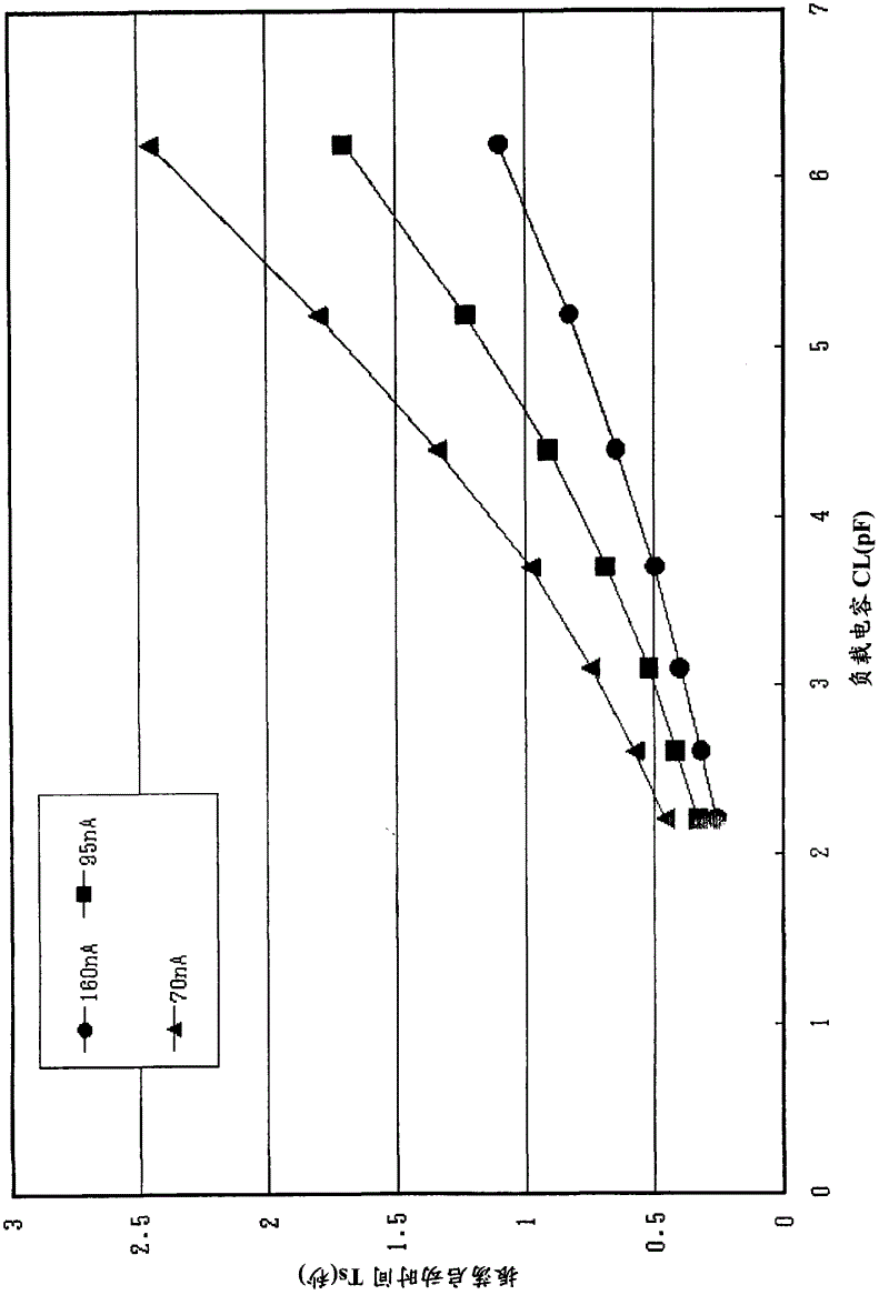
[0051] The purpose of the present invention is to provide a method to clarify the relationship between the oscillation start time and the load capacitance CL value of an oscillation circuit using a quartz oscillator, and to determine how much load capacitance CL value to use to set the desired oscillation start time That's good.

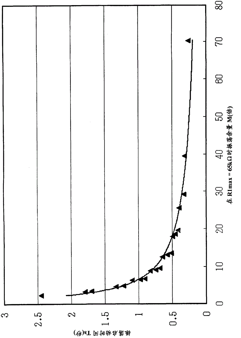
[0052] Oscillation startup time refers to the time until the oscillation waveform stabilizes (saturation) after the oscillation circuit with a crystal vibrator is installed in the equipment and the power is turned on, but from the viewpoint of measurement, it is defined as 90% of the amplitude of the normal waveform. % up to the time. figure 2 It is a graph showing the relationship between the aforementioned oscillation margin M and the oscillation start time Ts in various oscillation circuits including various crystal oscillators. From figure 2 It can be seen that the oscillation margin M becomes smaller as the oscillation start time becomes lon...


PUM


Abstract

There is provided an oscillation circuit using a crystal vibrator including means A for obtaining an oscillation activation time Ts (Ts0) from an oscillation margin M by using a relational equation between the oscillation activation time Ts and the oscillation margin M or a relational graph thereof; means B for obtaining a relational equation between the oscillation activation time Ts and a load capacitance CL in an arbitrary driving current value Ios from the relational equation between the oscillation activation time Ts and the load capacitance CL, and the driving current value Ios; and means C for determining the load capacitance CL corresponding to the oscillation activation time Ts0 obtained by the means A, by using the relational equation between the oscillation activation time Ts and the load capacitance CL, which is obtained by the means B.

Description

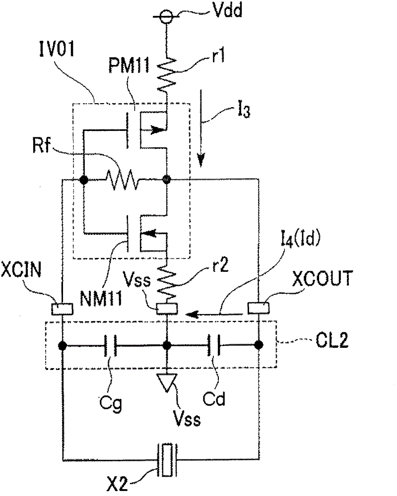
technical field [0001] The present invention relates to a method for realizing a low power consumption quartz (crystal) oscillating circuit, in particular to a method for determining the load capacitance constituting the quartz oscillating circuit and electronic equipment using the method. Background technique [0002] In portable devices such as clocks, mobile phones, etc., since the device is required to operate for a long time in a non-charging state or the frequency of charging the mounted battery is required to be reduced, it is increasingly necessary to reduce the frequency of the quartz oscillator used in the device. The driving power of the oscillation circuit of the piezoelectric element and ultra-low power consumption during the standby state of the oscillation circuit (in the state where the oscillation circuit oscillates and when there is no load) are achieved. [0003] image 3 A typical oscillation circuit using a quartz oscillator includes: a CMOS inverter IV0...

Claims


Application Information

Patent Timeline
Patent Type & Authority Applications(China)
IPC IPC(8): H03B5/32H03B5/06
CPCH03B5/06G01R31/2824H03B5/32G01R27/2605
Inventor 相马弘之
Owner SEIKO INSTR INC
Learn More