Temp controller and array waveguide lattice type optical wavelength multiplexer/demultiplexer

A temperature control device and temperature sensor technology, applied in the direction of temperature control, temperature control using digital devices, temperature control using electric means, etc., can solve the problem that the reliability of the temperature control device cannot be expected to be further improved, the efficiency of the temperature control device is deteriorated, The temperature control device has a complex structure and other problems, so as to achieve the effects of easy operation, reduced electric power consumption and simplified structure

Inactive Publication Date: 2006-12-06
SUMIDEN OPCOM +1
View PDF1 Cites 0 Cited by
  • Summary
  • Abstract
  • Description
  • Claims
  • Application Information

AI Technical Summary

Problems solved by technology

[0006] However, in the prior art described above, there is a problem that a higher junction temperature must be generated on the semiconductor control element 30 that directly controls the current supplied to the heater 40, so that the junction of the semiconductor control element 30 must be Therefore, the structure of the control unit 6 of the temperature control device becomes complicated, and at the same time, the miniaturization of the arrayed waveguide grating type optical wavelength multiplexer / demultiplexer using the temperature control device is also greatly affected. big limit
[0007] In addition, there is also the following problem: Since a part of the power supply electric power for heating and driving the heater 40 will be wasted as the junction temperature of the semiconductor control element 30, the loss in the semiconductor control element 30 becomes an ineffective part, thereby making the temperature control The overall efficiency of the device deteriorates
[0008] In addition, there is also a problem that the thermal resistance value of the semiconductor control element 30 (temperature increase rate per 1W) is the junction temperature, the temperature of the case of the arrayed waveguide grating type optical wavelength multiplexer / demultiplexer, and the thermal resistance value up to the air. , although it is the thermal resistance value as a heat sink (heat sink) from the temperature of the shell to the air, but it will become a higher value after miniaturization, so it is impossible to expect to further improve the reliability of the temperature control device

Method used


Image

  • Temp controller and array waveguide lattice type optical wavelength multiplexer/demultiplexer
  • Temp controller and array waveguide lattice type optical wavelength multiplexer/demultiplexer
  • Temp controller and array waveguide lattice type optical wavelength multiplexer/demultiplexer

Examples


Embodiment Construction

[0039] Next, the arrayed waveguide grating type optical wavelength multiplexer / demultiplexer of the present invention will be described with reference to the accompanying drawings.

[0040] Example.

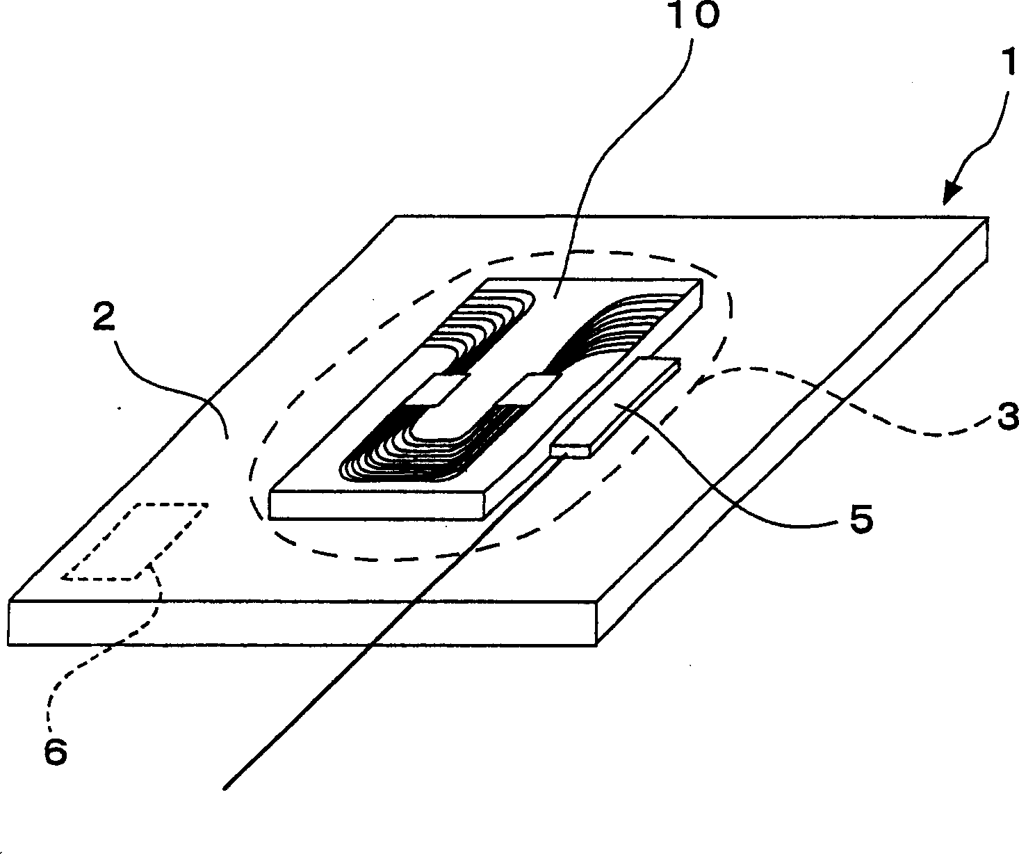
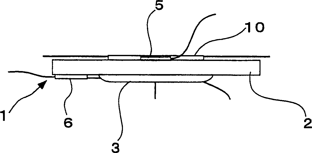
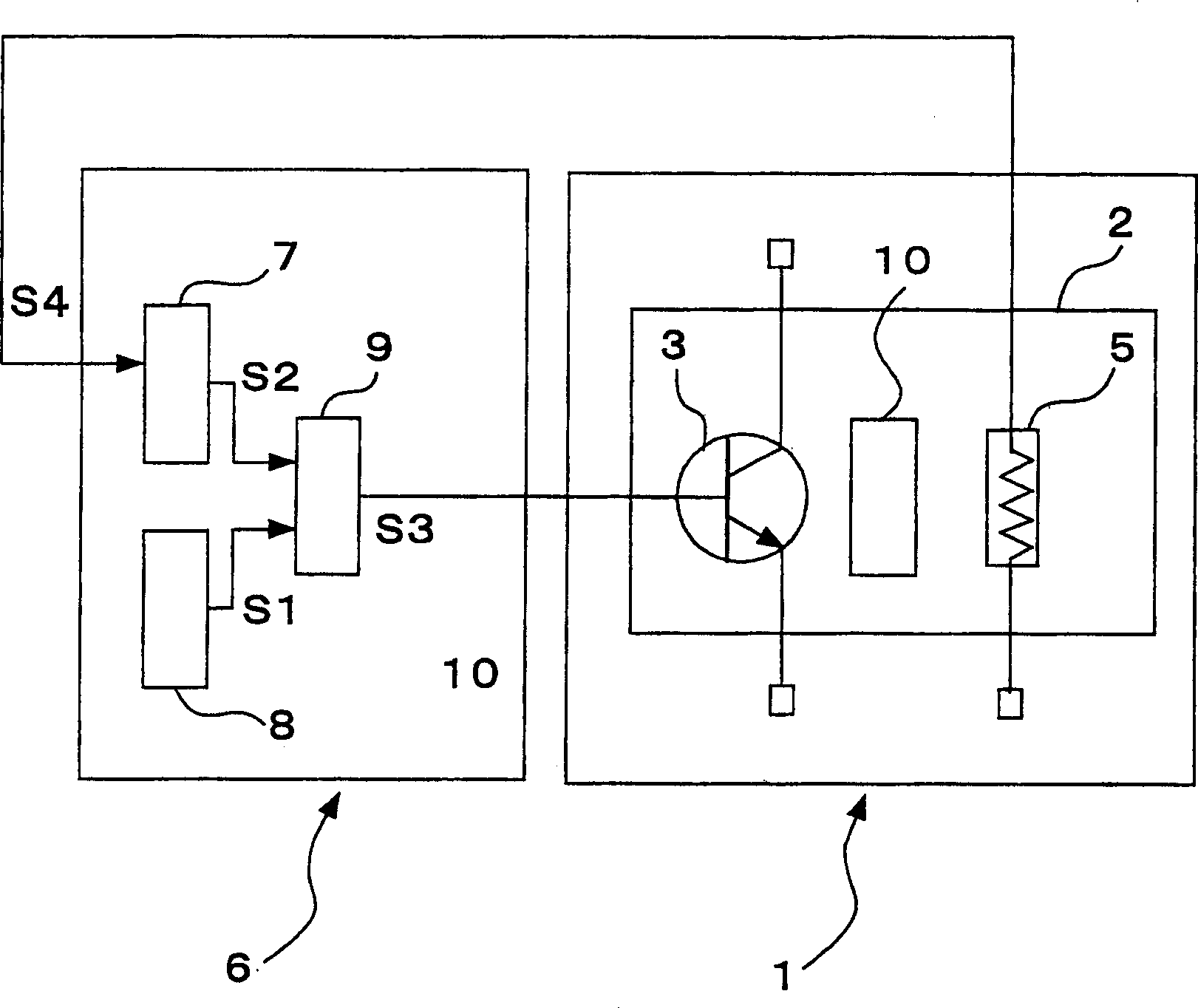
[0041] Figure 1 ~ Figure 3 It is a figure showing an embodiment, and the structure of the soaking part 1 of the temperature control device is as follows: figure 1 and figure 2As shown, on the upper surface of the vapor chamber 2 formed into a flat plate shape with a metal such as aluminum or copper or a material with good thermal conductivity such as sintered metal (ceramic), the characteristics will change as the temperature changes. Therefore, the The controlled body 10 of the arrayed waveguide grating type optical wavelength multiplexing / demultiplexing element that needs to be kept in a constant temperature state is bonded and fixed with a contact area as large as possible, and the temperature sensor 5 is grounded and fixed adjacent to the controlled body 10, and then the...


PUM


Abstract

In a temperature control device which maintains an obj ect to be controlled at a preset constant temperature and an arrayed waveguide grating optical wavelength multiplexer / demultiplexer, the adverse effect of the junction temperature of the semiconductor control element is eliminated for the purpose of simplifying the overall structure and improving operation efficiency sufficiently without any trouble. The object 10 to be controlled, which is an arrayed waveguide grating optical wavelength multiplexing / demultiplexing element, is fixed on the soaking plate 2 which is made from a good heat conductive material. The semiconductor control element 3 with a control terminal which functions as a heat generator by using its junction temperature and a temperature sensor 5 are fixed on the soaking plate 2. A negative feedback control is applied to the conduction condition of the semiconductor control element 3 in accordance with the error signal s3 which indicates the difference between the present temperature signal s2 obtained from the temperature detection signal s4 transmitted from the temperature sensor 5 and the preset target temperature signal s1. Consequently, the junction temperature of the semiconductor control element 3 is effectively used as a heating source not as a loss, thereby reducing the power consumption and stabilizing the performance.

Description

technical field [0001] The present invention relates to a temperature control device that finely heats controlled objects such as arrayed waveguide grating optical wavelength multiplexing and demultiplexing elements to keep them in a preset constant temperature state, and an arrayed waveguide grating optical fiber using the temperature control device. wavelength multiplexer. Background technique [0002] A general conventional structure of a temperature control device for maintaining a controlled object such as an arrayed waveguide grating type optical wavelength multiplexer / demultiplexer at a preset constant temperature is as follows: Figure 4 and Figure 5 As shown, it is composed of a heat soaking unit 1 and a control unit 6 . [0003] The structure of the soaking part 1 is that the heater 40 is buried on the soaking plate 2 made of a material with good thermal conductivity and the controlled object 10 is fixed, and the temperature sensor 5 is grounded and fixed adjacen...

Claims


Application Information

Patent Timeline
Patent Type & Authority Patents(China)
IPC IPC(8): G02B6/12H05B3/00G05D23/00G02B6/34G05D23/19
CPCG02B6/12026G02B2006/12135G05D23/1902G05D23/1917G02B6/12G05D23/00H05B3/00
Inventor 饭塚和夫渡边敏行生田纪之谷川尚伸汤浅隆继
Owner SUMIDEN OPCOM
Why Eureka
Try Eureka