Friction device and friction method for orientation film

A technology of friction device and alignment film, which is applied in nonlinear optics, instruments, optics, etc., can solve the problems of uneven friction effect of alignment film and achieve uniform friction effect

Inactive Publication Date: 2012-08-08
BEIJING BOE OPTOELECTRONCIS TECH CO LTD
View PDF9 Cites 11 Cited by
  • Summary
  • Abstract
  • Description
  • Claims
  • Application Information

AI Technical Summary

Problems solved by technology

[0004] Embodiments of the present invention provide an alignment film rubbing device and a rubbing method, which are used to solve the rubbing effect of the alignment film caused by rubbing the alignment film of an array substrate provided with at least two pixel electrodes arranged in different directions. uneven problem

Method used


Image

  • Friction device and friction method for orientation film
  • Friction device and friction method for orientation film
  • Friction device and friction method for orientation film

Examples


Embodiment 1

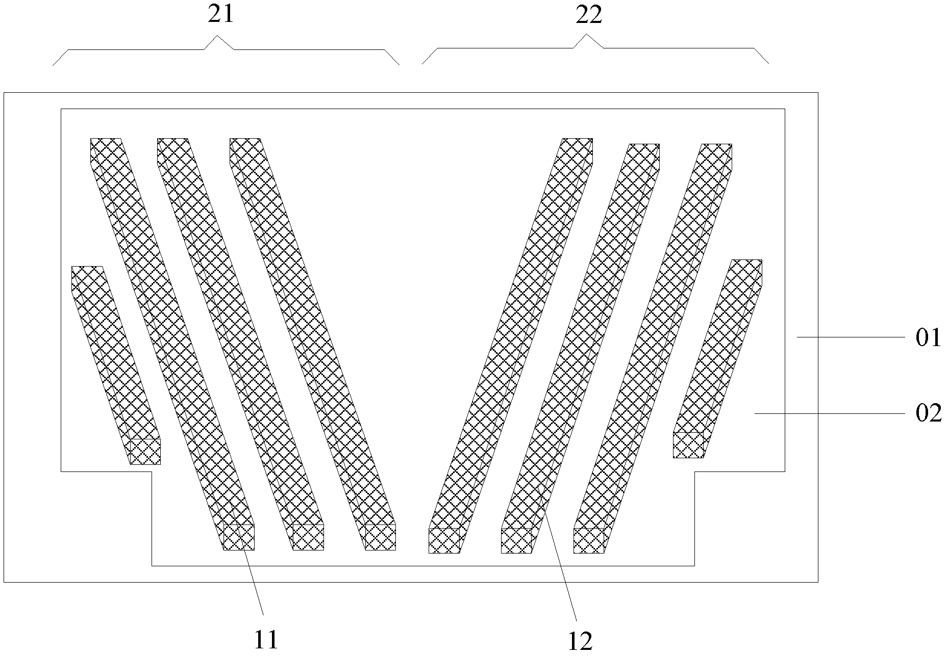
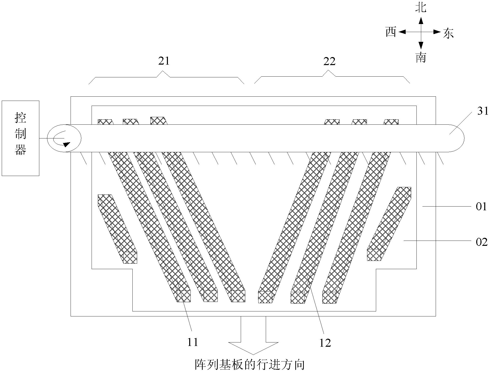
[0038] The above-mentioned alignment film rubbing device will be described in detail below for specific situations. The specific circumstances are as figure 2 As shown, the alignment film rubbing device includes a rubbing roller 31, and the rubbing roller 31 rubs the alignment film 02 of the array substrate 01 provided with two pixel electrodes arranged in different directions. In the embodiment of the present invention, the array substrate is provided with two pixel electrodes arranged in different directions, that is, the first pixel electrode 11 and the second pixel electrode 12 .

[0039] Such as figure 2 In the schematic diagram of rubbing the alignment film shown, the rubbing device for the alignment film includes: a rubbing roller 31, on which a rubbing cloth is attached; friction.

[0040] For one of the pixel electrodes on the array substrate, the inclination direction of the fluff of the rubbing cloth on the rubbing roller is consistent with the arrangement direct...

Embodiment 2

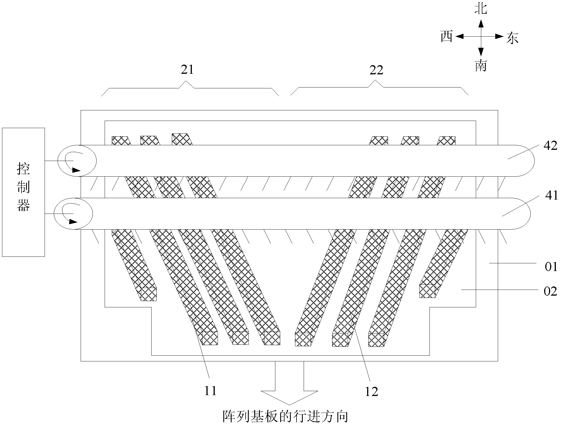
[0054] Embodiments of the present invention provide another alignment film rubbing device and rubbing method. Such as image 3 As shown, the alignment film rubbing device includes two rubbing rollers, namely a first rubbing roller 41 and a second rubbing roller 42; the rubbing rollers 41, 42 are paired with an array substrate 01 with two pixel electrodes arranged in different directions. The alignment film 02 is rubbed. In the embodiment of the present invention, the array substrate is provided with two pixel electrodes arranged in different directions, that is, the first pixel electrode 11 and the second pixel electrode 12 .

[0055] Such as image 3 In the shown orientation film rubbing diagram, the alignment film rubbing device includes: two rubbing rollers 41, 42, on which rubbing cloth is attached; the two rubbing rollers 41, 42 are used to align the array The alignment film 02 of the substrate 01 is rubbed twice.

[0056] Wherein, the two rubbing rollers 41 and 42 ar...

Embodiment 3

[0067] Embodiments of the present invention provide another alignment film rubbing device and rubbing method. Such as Figure 4 As shown, the alignment film rubbing device includes two rubbing rollers, namely a first rubbing roller 51 and a second rubbing roller 52; Make a rub. In the embodiment of the present invention, the array substrate is provided with two pixel electrodes arranged in different directions, that is, the first pixel electrode 11 and the second pixel electrode 12 .

[0068] Such as Figure 4 In the shown orientation film rubbing diagram, the alignment film rubbing device includes: two rubbing rollers 51, 52, on which rubbing cloth is attached; the two rubbing rollers 51, 52 are used to align the array The alignment film 02 of the substrate 01 is rubbed twice.

[0069] Wherein, the two rubbing rollers are used to rub the alignment film 02 of the array substrate 01 twice, which means that the first rubbing roller 51 rubs the alignment film 02 of the array ...


PUM


Abstract

An embodiment of the invention discloses a friction device and a friction method for an orientation film, which relate to the field of liquid crystal display and are used for solving the problems that a friction effect for the orientation film is not even if the orientation film is provided with an array substrate with pixel electrodes in at least two different directions. The friction method for the orientation film includes that at least one friction roller is used for conducting at least two times of friction on the orientation film of the array substrate, and at least two groove marks are left on the orientation film of the array substrate. Friction cloth is arranged on the friction roller, the pixel electrodes in at least two different arrangement directions are arranged on the array substrate. The directions of the at least two groove marks correspond to arrangement directions of the pixel electrode in at least two different arrangement directions one by one, and two corresponding directions are the same. The scheme is applicable to friction process of the orientation film in a production process of a liquid crystal display panel.

Description

technical field [0001] The invention relates to the field of liquid crystal display, in particular to an alignment film rubbing device and a rubbing method. Background technique [0002] Displays with wide viewing angles, high contrast ratio, and low power consumption are attracting more and more attention. In order to achieve an ultra-wide viewing angle and improve display quality, various implementation schemes have been designed. [0003] Such as figure 1 As shown, it is an array substrate of a display, and the arrangement directions of two (or three or more) pixel electrodes in a sub-pixel structure are different; The inclined pixel electrode is called the first pixel electrode 11 , and the pixel electrode inclined to the right of the symmetrical axis of the two pixel electrodes is called the second pixel electrode 12 . The first pixel electrode 11 and the second pixel electrode 12 in each sub-pixel structure are protruding strip structures, that is, the surface of th...

Claims


Application Information

Patent Timeline
Patent Type & Authority Applications(China)
IPC IPC(8): G02F1/1337
Inventor 肖昂宋省勳刘文智马俊才高翔
Owner BEIJING BOE OPTOELECTRONCIS TECH CO LTD
Why Eureka
Try Eureka