Deformation-controllable bionic joint based on friction effect and its preparation method and application

A bionic joint and friction effect technology, applied in the field of structural bionics, can solve the problems of complex structure, poor compatibility of human body structure, inability to realize multi-segment fixed-point deformation, etc., and achieve the effect of simple material and uniform friction effect

Active Publication Date: 2021-08-03
HUAZHONG UNIV OF SCI & TECH
View PDF7 Cites 0 Cited by
  • Summary
  • Abstract
  • Description
  • Claims
  • Application Information

AI Technical Summary

Problems solved by technology

[0002] Most of the existing bionic joints are designed with hardware structures such as bearings, springs, and connecting rods. The structures are complex, and most of them need to be used in conjunction with external control equipment, which is poorly compatible with human body structures.
Even in the field of clinical medicine, although there are bionic structures compatible with the human body such as artificial bones, various types of intracavitary stents, thrombus filters, embolizers, etc., such structures are generally relatively simple, such as artificial bones, which can only bionic single Segmental bones cannot be bionically connected to multiple bones that can be bent, and most bionic structures are deformed by receiving external stimuli. Therefore, certain environmental conditions need to be set outside the bionic structure, which greatly limits the application range and development of bionic structures. It is an internal heating stimulus, and it can only stimulate deformation at a single point and cannot achieve multi-segment fixed-point deformation. The existing design cannot meet the requirements of multi-segment deformation, especially in the field of bionic joints. For example, bionic fingers are often multi-joint structures and require internal active control. Therefore, based on the above problems, it is urgent to design a bionic joint that can actively control multi-segment deformation from the inside

Method used


Image

  • Deformation-controllable bionic joint based on friction effect and its preparation method and application
  • Deformation-controllable bionic joint based on friction effect and its preparation method and application
  • Deformation-controllable bionic joint based on friction effect and its preparation method and application

Examples


Embodiment

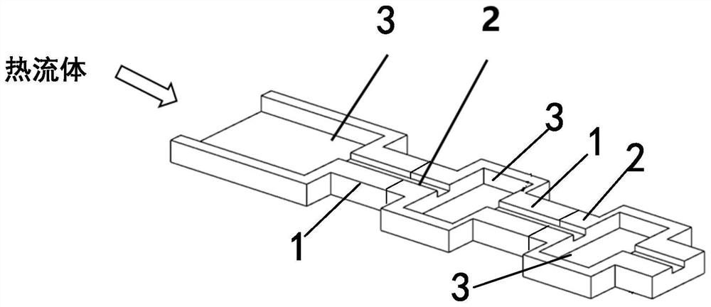
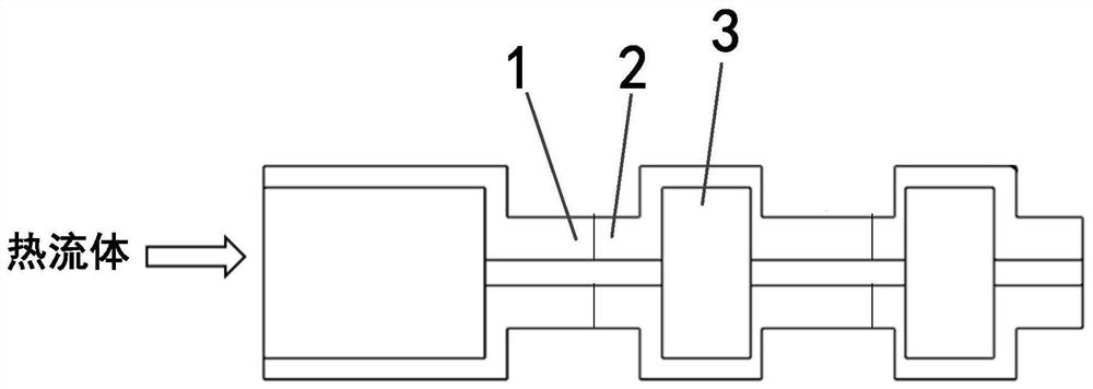
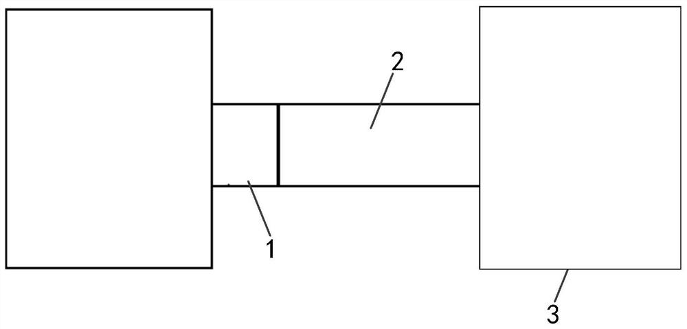
[0041] The embodiment of the present disclosure is the bionic of the elbow joint of the arm. Since the elbow joint is a straight section connected to a curved section and then connected to a straight section, a set of heating section, deformation section and cooling section can be used. The length of the heating section is the length of the forearm of the arm, and the length of the cooling section is the length of the forearm of the arm. The internal fluid is water, and the material of the deformation section is NiTi shape memory alloy. Since the phase transition temperature of NiTi shape memory alloy varies greatly with the composition ratio and process parameters, the deformation critical temperature of the material is taken as 80°C (specifically The value is determined by the composition ratio and process parameters). Comprehensively consider the influence of the pipe diameter on the unit temperature rise and the initial water temperature, for example, the pipe diameter is ...


PUM


Abstract

The invention belongs to the technical field related to structural bionics, and discloses a bionic joint with controllable deformation based on friction effect and its preparation method and application. , wherein the material of the deformation section is a shape memory alloy, the inner wall of the heating section is a heat insulating material, and the material of the cooling section is a heat conducting material. When flowing through the deformation section, the deformation section is deformed, and the fluid flowing out from the deformation section passes through the cooling section to dissipate heat and cool down. The present application realizes the deformation requirement of multiple deformation segments in the bionic structure, so that the bionic structure can be actively controlled.

Description

technical field [0001] The invention belongs to the technical field related to structural bionics, and more specifically relates to a bionic joint with controllable deformation based on friction effect and its preparation method and application. Background technique [0002] Most of the existing bionic joints are designed with hardware structures such as bearings, springs, and connecting rods. The structures are complex, and most of them need to be used in conjunction with external control equipment, which has poor compatibility with human body structures. Even in the field of clinical medicine, although there are bionic structures compatible with the human body such as artificial bones, various types of intracavitary stents, thrombus filters, embolizers, etc., such structures are generally relatively simple, such as artificial bones, which can only bionic single Segmental bones cannot be bionically connected to multiple bones that can be bent, and most bionic structures are...

Claims


Application Information

Patent Timeline
Patent Type & Authority Patents(China)
IPC IPC(8): A61F2/30A61F2/42A61F2/44
CPCA61F2/30A61F2/30942A61F2/42A61F2/4241A61F2/44A61F2002/30039A61F2002/30046A61F2002/30065A61F2002/30092
Inventor 宋波阚隆鑫史玉升
Owner HUAZHONG UNIV OF SCI & TECH
Why Eureka
Try Eureka