Seal structure of electric kettle

A technology of sealing structure and electric kettle, which is applied to water boiling utensils, cooking utensils, household utensils, etc. It can solve the problems of high cost, difficult assembly, and poor sealing, so as to improve quality, reduce cost, and prevent poor sealing. Strict effect

Active Publication Date: 2012-08-15
徐智慧 +1
View PDF6 Cites 34 Cited by
  • Summary
  • Abstract
  • Description
  • Claims
  • Application Information

AI Technical Summary

Problems solved by technology

In the process of boiling water, the spring may be compressed by the gravity of the water, causing the seal to be

Method used


Image

  • Seal structure of electric kettle
  • Seal structure of electric kettle
  • Seal structure of electric kettle

Examples


no. 1 example

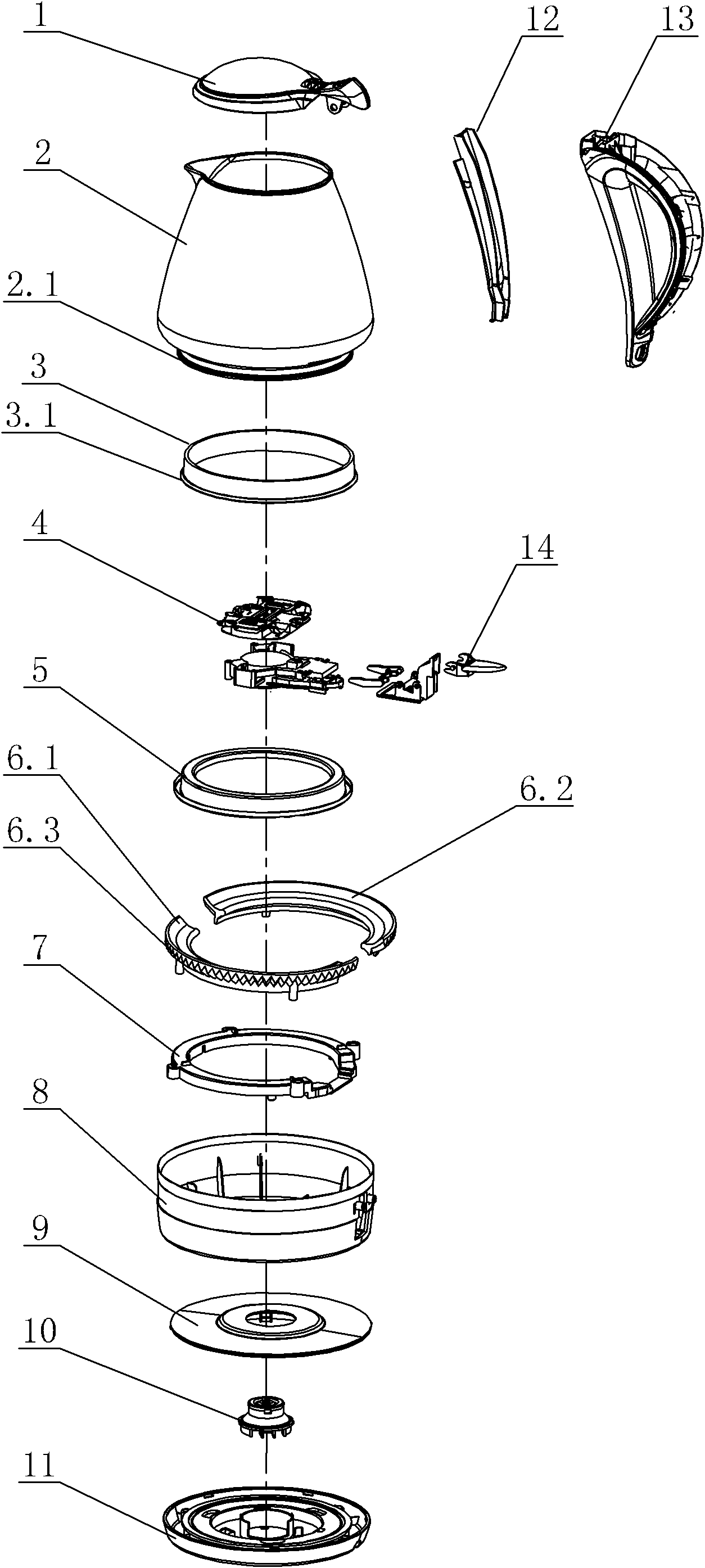
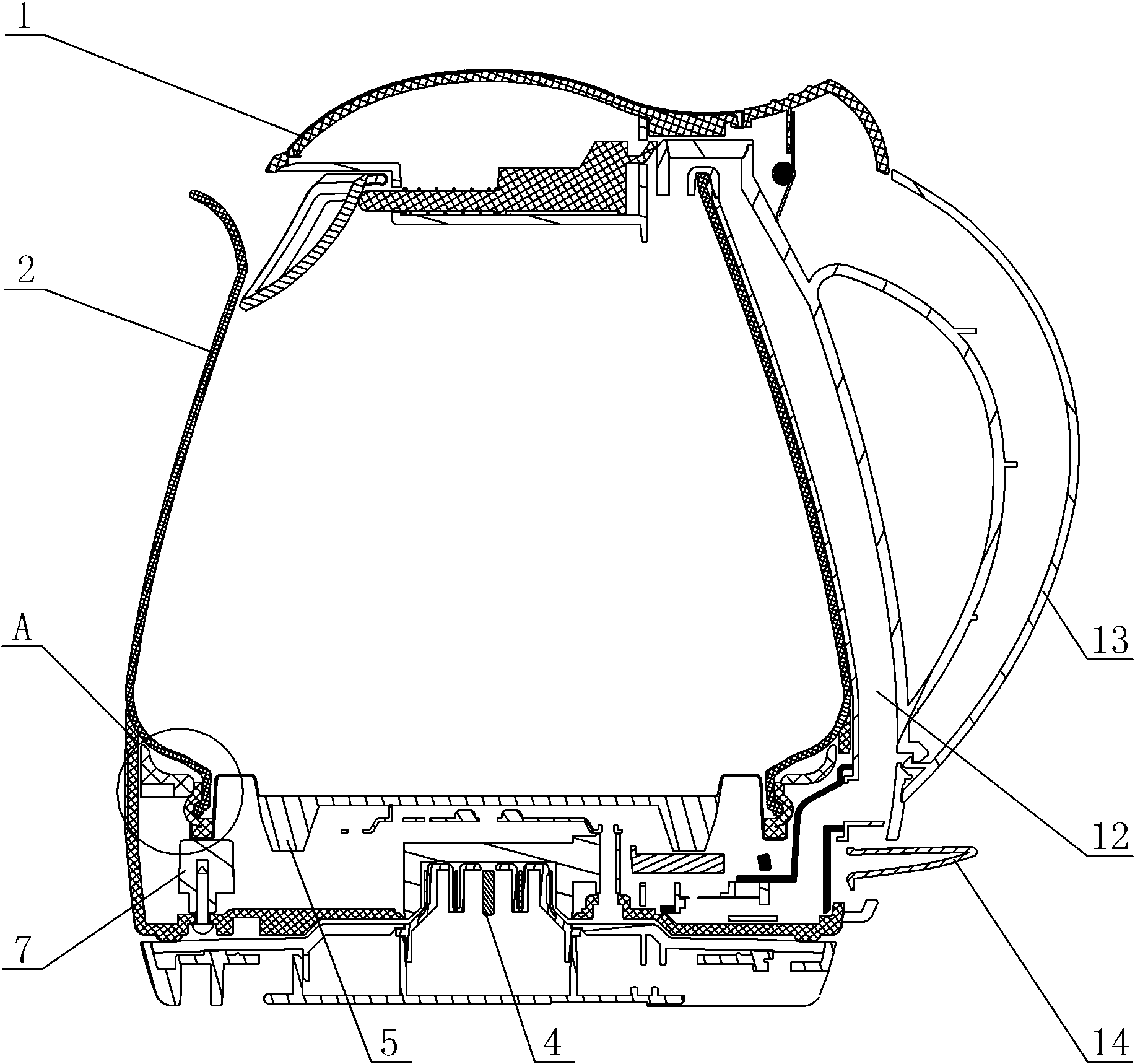
[0028] see Figure 1-Figure 5 , the sealed structure of the electric kettle includes a main body 2 with a handle 13 and its bottom cover 8, the handle 13 and the main body 2 are separated, and a steam channel 12 is arranged between the handle 13 and the main body 2, and the steam channel 12 communicates with the inner cavity of the main body 2, and the material of the main body 2 is glass. The handle 13 is provided with a cover body 1 hingedly fixed thereto, and the cover body 1 is rotatably connected with the main body 2 . A heating element 5 is arranged in the main body 2, and the heating element 5 is a heating plate. The bottom cover 8 is provided with a thermostat assembly 4 electrically connected to the heating element 5 , a switch button 14 and a power connection assembly. The power connection assembly is movably connected with the bottom cover 8, and the power connection assembly is assembled by the power supply upper cover 9 and the power supply lower cover 11. A co...

no. 2 example

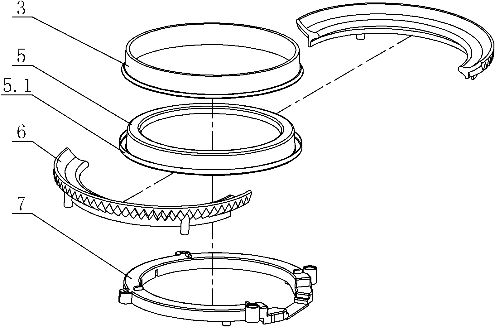
[0033] see Figure 6-Figure 8 , The silicone seal ring 3 is provided with an inlay portion with an upward opening, or the silicone seal ring 3 is provided with a contact surface that gradually increases or is equal in size from top to bottom to match the body opening 2.1. The main body opening 2.1 on the main body 2 is inserted into the inlay part, and the cross section of the main body opening 2.1 is straight, bent or inclined. The silicone sealing ring 3 is wrapped on the lower part of the main body 2 to realize double-layer sealing effect between the main body 2 and the heating element 5 and further improve the sealing performance. Other unmentioned parts are the same as the first embodiment.

no. 3 example

[0035] see Figure 9-Figure 12, the outer side of the silicone sealing ring 3 is set as a shrinkage band 31 or a metal tie wire 32 to fix the heating element 5 and the body 2 in a sealed connection, the shrinkage band 61 or the metal tie wire 62 is in the shape of a ring with an opening, the shrinkage band or The two ends of the metal binding wire are tightened and together form a closed ring, circle or ellipse. Two connecting pieces 62.2 are arranged on the metal binding wire, and the connecting pieces 62.2 are connected with the top ring through fasteners. Shrink band 61, or metal binding wire 62, or clasp and top ring 7 fixed sealing parts are lifted upwards, and sealing parts are provided with gradually larger or equal contact surfaces from top to bottom to cooperate with the opening of the body 2 to form a Leakproof body with heated bottom. Other unmentioned parts are the same as the first embodiment.


PUM


Abstract

A seal structure of an electric kettle comprises a body with a handle and a bottom cover of the body. A heating element is disposed in the body. The body is provided with a body opening corresponding to the heating element. A seal part is disposed at the connection of the body opening with the heating element. The seal part or the body is provided with a snap ring outside. The snap ring for fixing the heating element is hermetically connected with the body, or the seal part or the body is provided with a retractable strip, or a metal tying wire for fixing the heating element is hermetically connected with the body. The seal part is provided with a groove part with an upward opening, or the inner wall of a silicone seal ring and the outer wall of the heating element form a groove part with an upward opening, or a contact face of the seal part is in extrusion-deforming fit with the cross section of the body opening. The seal part is added to the heating element and provided with the snap ring, the retractable strip or the metal tying wire outside, and accordingly the heating element is hermetically connected with the body, poor tightness, seepage and the like are effectively prevented, and product quality is improved.

Description

technical field [0001] The invention relates to an electric kettle, in particular to a sealing structure of the electric kettle. Background technique [0002] The electric kettle is one of the commonly used small household appliances, which is used for heating water and can be used as a container for water at the same time, and has the characteristics of easy use. The bottom of the electric kettle is equipped with an electric heating device. Earlier, the heating device was an electric heating tube that protruded upwards from the bottom of the container to heat the water in the container. If exposed to water, it is easy to get rusted due to corrosion, and finally it is damaged and cannot be used, and it affects hygiene. [0003] In view of the above problems, designers in the industry have designed an electric heating device with a flat heating surface. The flat heating surface forms the bottom of the heating container, which is heated by direct contact with water. Therefor...

Claims


Application Information

Patent Timeline
IPC IPC(8): A47J27/21A47J36/00
CPCA47J27/2105A47J27/21A47J27/21166
Inventor 徐智慧周林斌
Owner 徐智慧
Why Eureka
Try Eureka