
Worktable of cutting machine

A workbench and cutting machine technology, applied in the direction of manufacturing tools, metal processing equipment, metal processing machinery parts, etc., can solve the problems of high labor intensity, poor cutting precision, low precision, etc., to improve safety and service life, smooth Straight line and bending movement, the effect of reducing labor intensity

Active Publication Date: 2012-08-15
NINGBO XINTAI MACHINERY
View PDF4 Cites 1 Cited by
  • Summary
  • Abstract
  • Description
  • Claims
  • Application Information

AI Technical Summary

Problems solved by technology

When the cutting machine is switched to cut the curved product after cutting the straight product, or switched to cutting the straight product after cutting the curved product, it often takes a lot of time to move and adjust the position of the cutting machine. This process greatly In order to affect the efficiency of production, increase the labor intensity of workers
At the same time, due to the frequent adjustment of the cutting machine, the production accuracy is not high, resulting in a lot of waste
The existing cutting and conversion methods generally adopt two methods: one is to directly transport the equipment to the position where it needs to be cut and cut it; Although method 1 is simple, it is labor-intensive during the handling process, the process of cutting the product is very unstable, and the accuracy is poor; method 2 is labor-intensive during the handling process, but it is troublesome to replace. Sometimes it is necessary to use a cylinder or a spring to always push against the template. Due to structural defects, it is still very unstable during the cutting process, and the cutting accuracy is poor, and the faster the production line is, the worse the accuracy is, causing a large number of products to be scrapped.
Both methods have the problems of high labor intensity, poor precision and long switching time

Method used


Image

  • Worktable of cutting machine
  • Worktable of cutting machine
  • Worktable of cutting machine

Examples


Embodiment Construction

[0028] The present invention will be further described in detail below in conjunction with the accompanying drawings and embodiments.

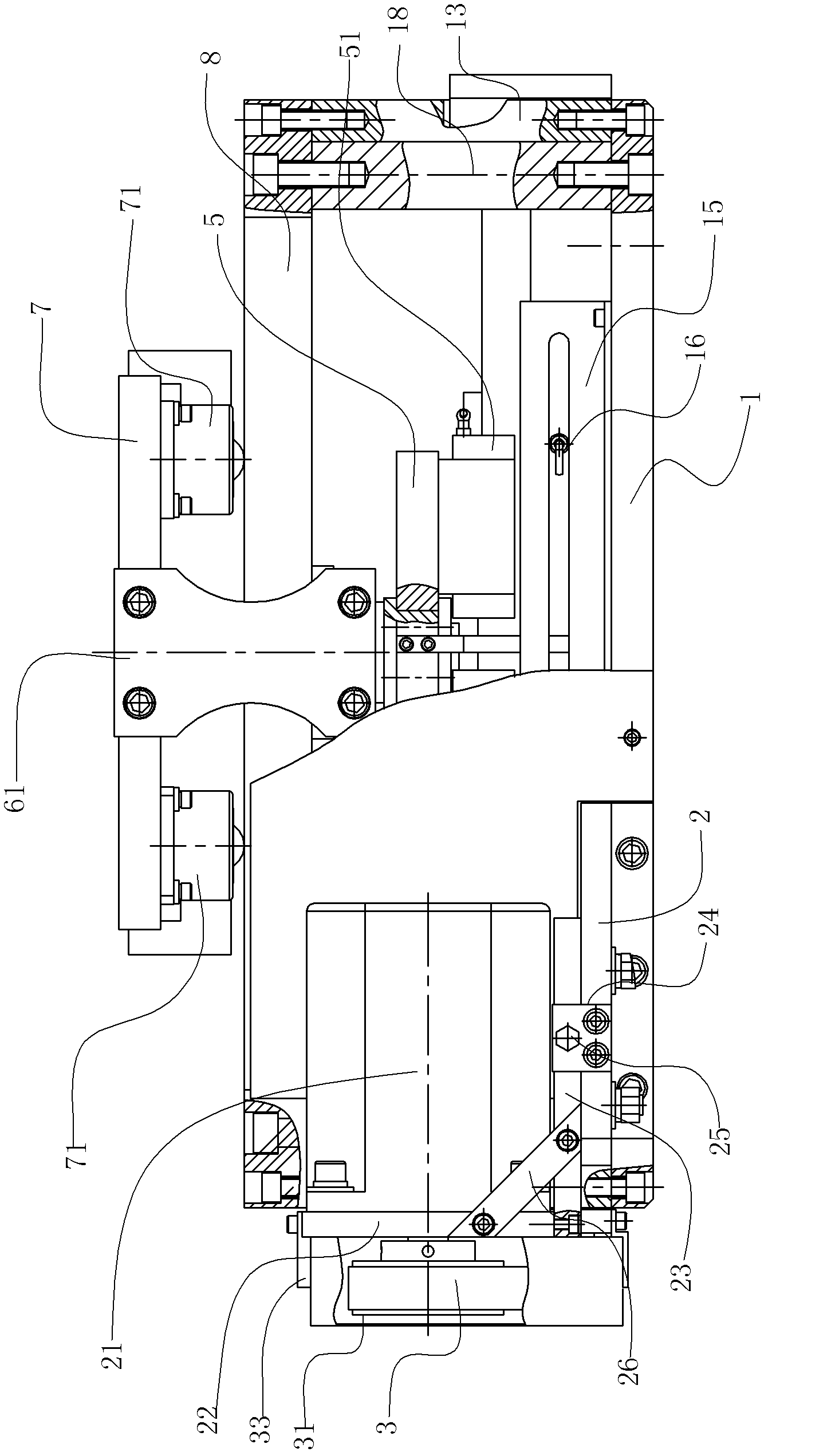
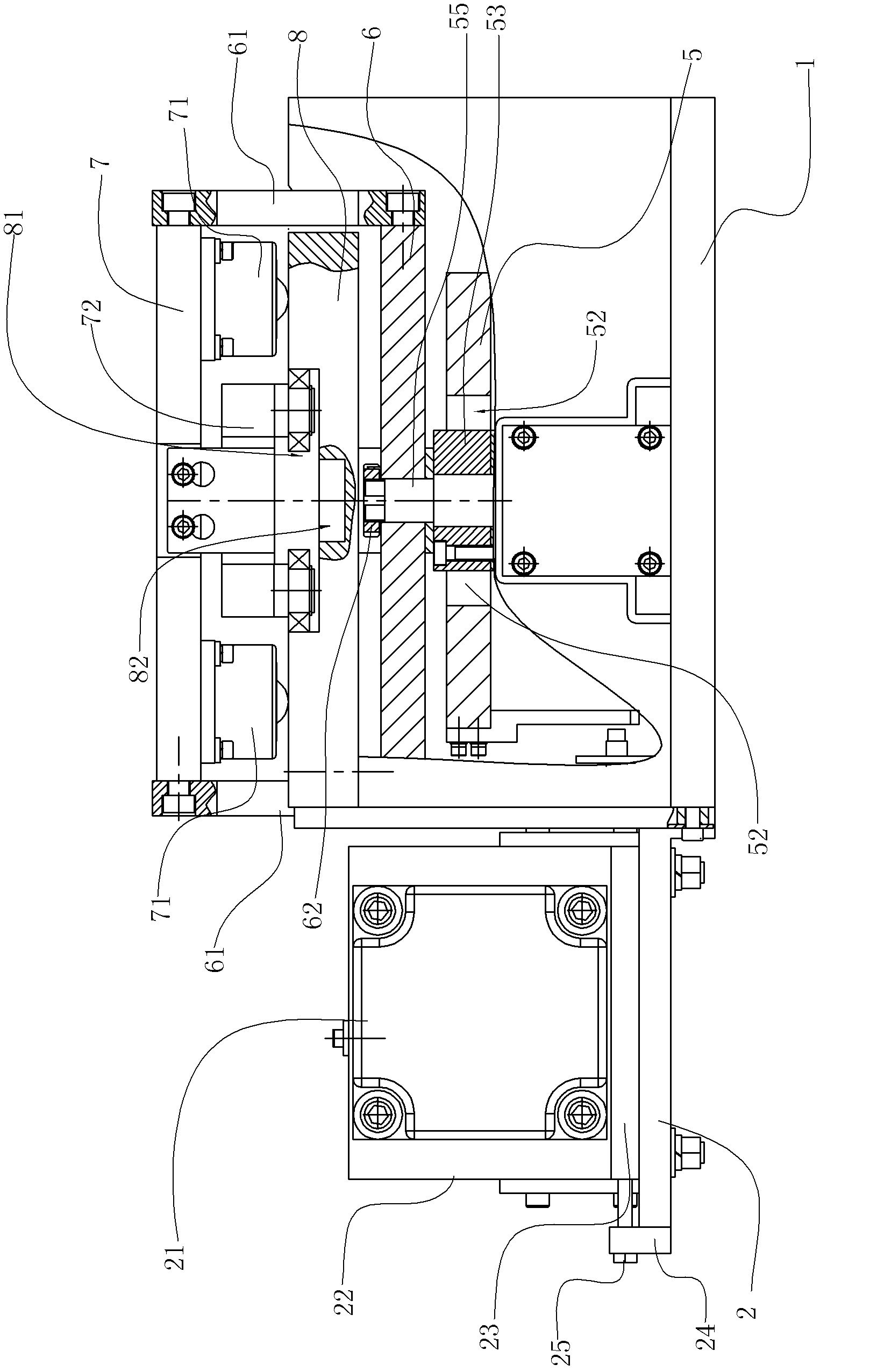
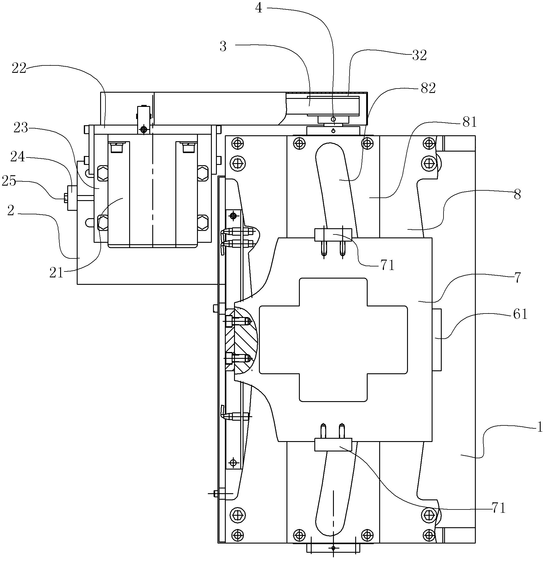
[0029] Cutting machine table of the present invention, as Figure 1-7 As shown, it includes a horizontally arranged system backplane 1 and a motor 21 located on one side of the system backplane 1, the side of the motor 21 is fixed on a vertical motor fixing plate 22, and the bottom of the motor fixing plate 22 and the motor 21 is provided with The motor moving plate 23, the motor fixing plate 22 and the motor moving plate 23 are fixed to limit the position of the motor 21, the motor moving plate 23 is horizontally arranged on the top of a mobile support 2, and one side of the mobile support 2 is connected to the system bottom plate 1. One side is fixedly connected, that is, the system base plate 1 and the mobile bracket 2 are arranged horizontally adjacent to each other, and the mobile bracket 2 is horizontally provided with a motor moving pla...


PUM


Abstract

A worktable of a cutting machine comprises a system bottom plate and a motor. A lead screw transmission shaft is horizontally arranged on the system bottom plate, a nut is fixedly sleeved on the outside of the lead screw transmission shaft and fixed to the lower portion of a lead screw and nut connecting plate, a moving substrate which is horizontally arranged, positioned above the lead screw transmission shaft and spaced from the lead screw transmission shaft is fixed to the top of the lead screw and nut connecting plate, a transmission plate and a moving platform are arranged above the moving substrate by a distance, the transmission plate is parallel to the moving substrate, the moving platform is horizontally supported on the upper side of the transmission plate and is spaced from the transmission plate, and a guide plate is further horizontally disposed between the transmission plate and the moving platform. The worktable not only can be used for cutting straight materials, but also can be used for cutting bent materials, the frequency of change among the straight materials and the bent materials is reduced, switching time is greatly saved, labor intensity is reduced, the safety of a product is improved, the service life of the product is prolonged, and the cutting precision of the product is guaranteed.

Description

technical field [0001] The invention relates to a cutting machine, in particular to an accompanying workbench of the cutting machine. Background technique [0002] In modern production and processing, especially in the automotive industry, products are often cut, and some of the products are straight sheet metal materials, and some are bent sheet metal materials. When the cutting machine is switched to cut curved products after cutting straight products, or switched to cutting straight products after cutting curved products, it often takes a lot of time to move and adjust the position of the cutting machine. This process greatly In order to affect the efficiency of production, increase the labor intensity of workers. At the same time, due to the frequent adjustment of the cutting machine, the production accuracy is not high, resulting in a large amount of waste. The existing cutting and conversion methods generally adopt two methods: one is to directly transport the equipm...

Claims


Application Information

Patent Timeline
Patent Type & Authority Applications(China)
IPC IPC(8): B23Q1/25
Inventor 胡剑英
Owner NINGBO XINTAI MACHINERY
Learn More