Visual worktable for workpiece conveying on catenary

A catenary and worktable technology, which is applied in the direction of conveyor objects, transportation and packaging, conveyor control devices, etc., can solve the problem that workpieces cannot be hung on the catenary, loading and unloading workers have high labor intensity, and are not suitable for mass production and other problems, to achieve the effect of simple structure, short working time and convenient operation

Inactive Publication Date: 2012-08-15
UNIV OF JINAN +1
View PDF8 Cites 27 Cited by
  • Summary
  • Abstract
  • Description
  • Claims
  • Application Information

AI Technical Summary

Problems solved by technology

[0002] At present, the handling of workpieces on the catenary production line is basically done manually. The loading and unloading workers have high labor intensity

Method used


Image

  • Visual worktable for workpiece conveying on catenary
  • Visual worktable for workpiece conveying on catenary
  • Visual worktable for workpiece conveying on catenary

Examples


Embodiment Construction

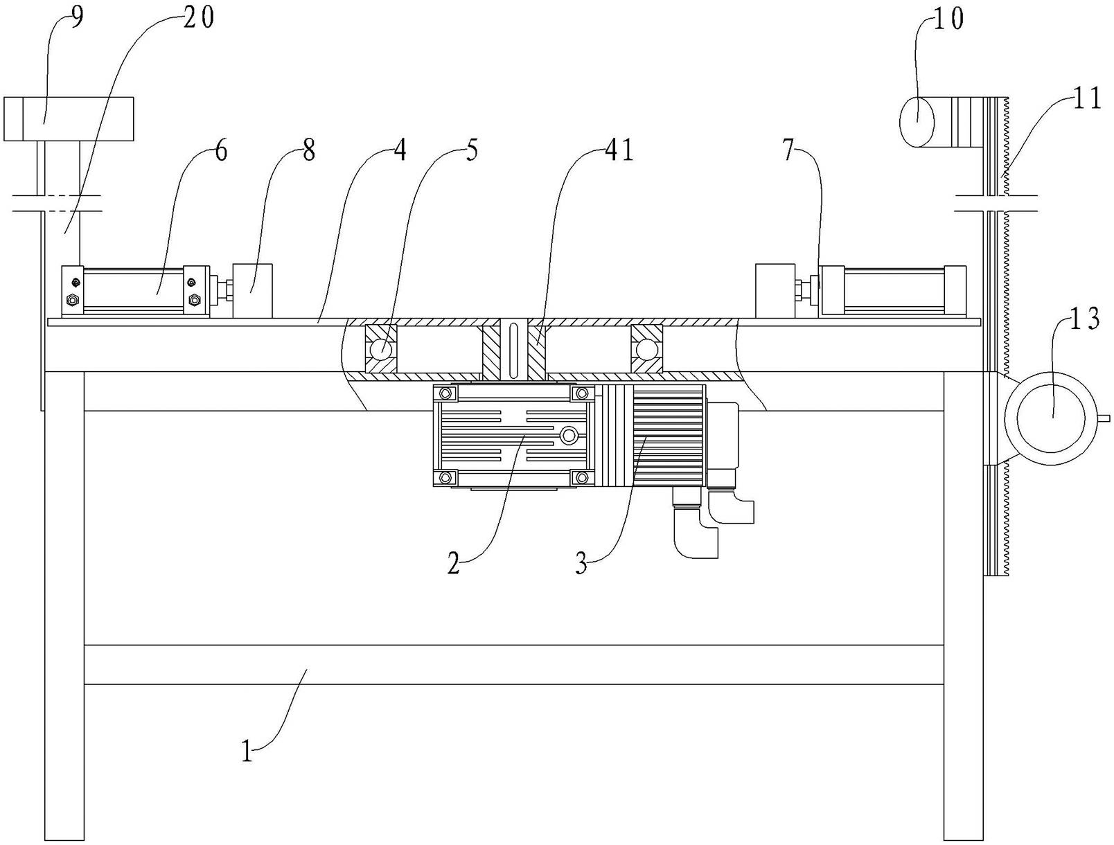
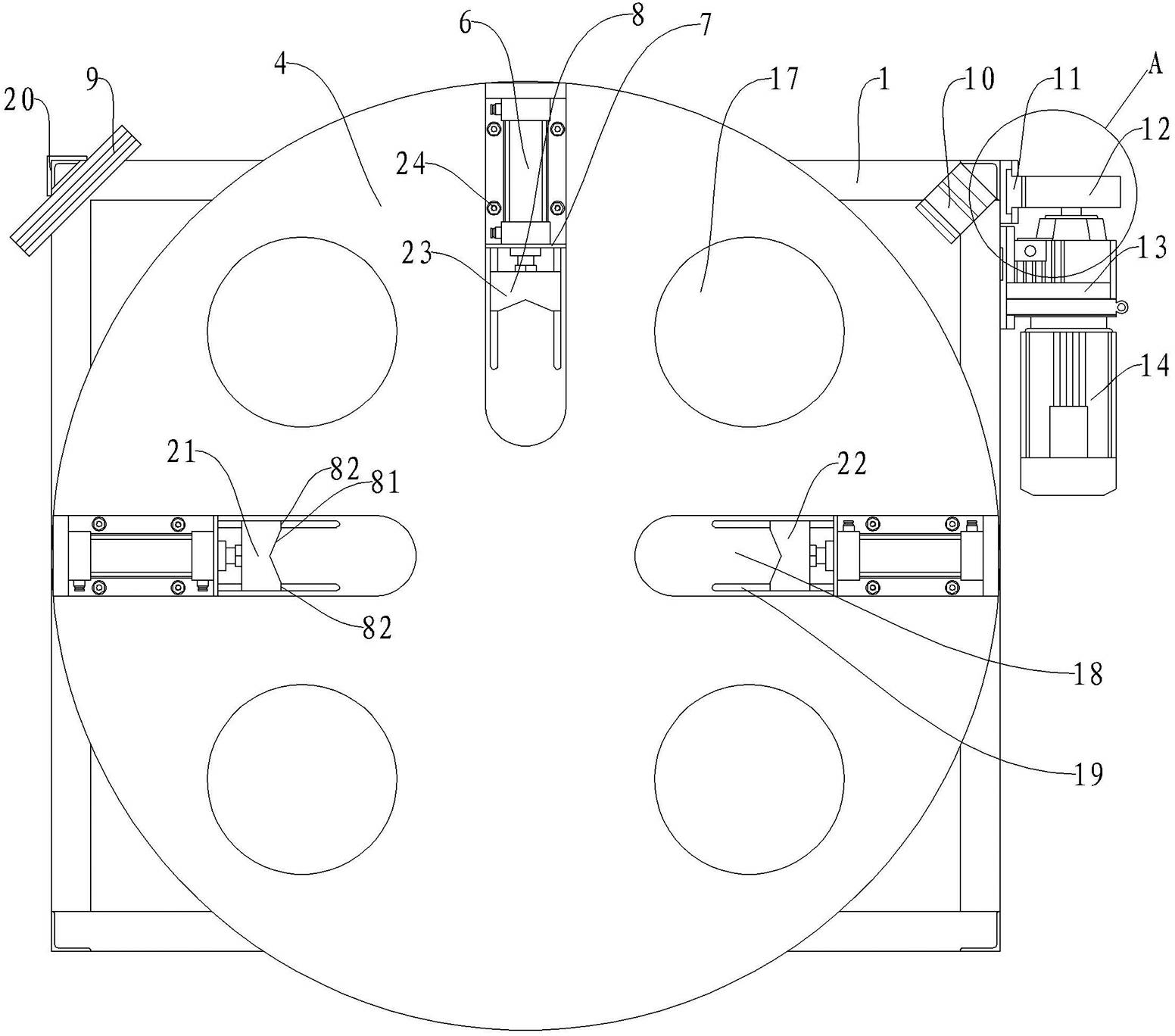
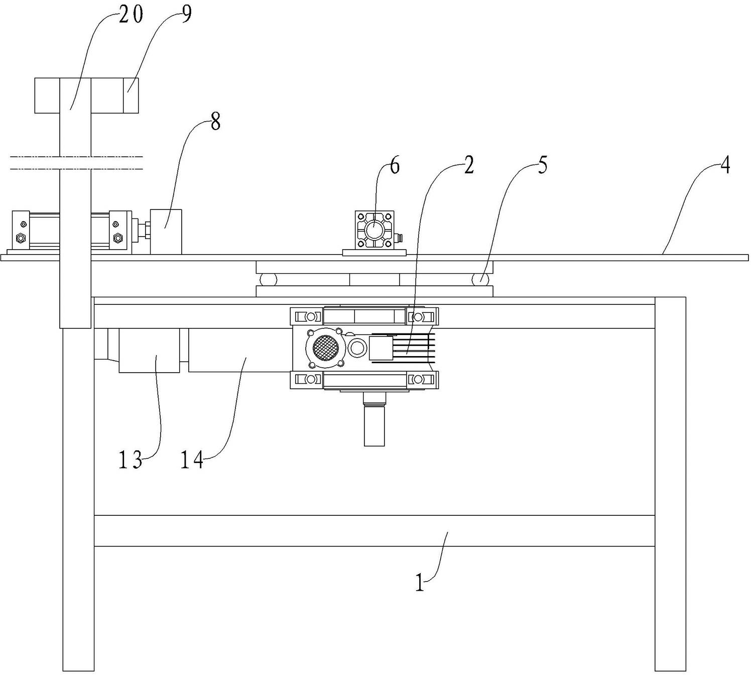
[0025] Such as figure 1 , 2 , 3, the vision workbench for workpiece handling on the catenary mainly includes a workbench 1, a turntable 4, a turntable driving device, and a machine vision system.

[0026] The turntable 4 is arranged above the workbench through the central axis 41 .

[0027] The turntable driving device includes a servo motor 3 and a speed reducer 2 for rotation, and the servo motor 3 and the speed reducer 2 for rotation are fixed on the workbench 1 and are located below the turntable 4 . The rotation is connected by a key between the output shaft of the speed reducer 2 and the central shaft 41 of the turntable. The servo motor drives the turntable to rotate around the central axis through the rotation reducer.

[0028] Because the diameter of the output shaft of the reducer 2 and the central shaft 41 of the turntable are small, the diameter of the turntable is relatively large (the turntable is about 1.2 meters in diameter during actual production), so the ...


PUM


Abstract

The invention discloses a visual worktable for workpiece conveying on a catenary, which at least comprises a worktable frame, a rotary table, a rotary table drive device and a machine vision system, wherein the upper surface of the rotary table is used for placing workpieces, the rotary table is provided with a fixture for clamping workpieces, and the rotary table is arranged above the worktable frame through a central shaft; the rotary table drive device is used for driving the rotary table to rotate around the central shaft; and the machine vision system is used for continuously acquiring an image of the surface of a workpiece on the rotary table and finding out a preset feature part of the workpiece in the rotating process of the rotary table, thereby obtaining a positioning rotating angle required by the forward or reverse rotation of the rotary table in the process of workpiece positioning according to the rotating angle of the rotary table when the feature part of the workpiece is measured, and outputting a control signal to the rotary table drive device to drive the rotary table to rotate forwardly or reversely for the positioning rotating angle so as to drive the workpiece to rotate to a correct orientation. The worktable can rotate a conveyed workpiece or a workpiece placed on the worktable to rotate a corresponding angle so as to provide an ideal workpiece orientation for an automatic conveying device, so that the automatic conveying device can be accurately hung on a catenary production line.

Description

technical field [0001] The invention relates to the technical field of catenary production lines, in particular to a workbench for transporting workpieces on catenary lines. Background technique [0002] At present, the handling of workpieces on the catenary production line is basically done manually. The loading and unloading workers have high labor intensity and low loading and unloading efficiency. , so it is impossible to correctly hang arbitrarily placed workpieces on the catenary with simple handling equipment. Contents of the invention [0003] In order to overcome the above-mentioned shortcomings in the prior art, the object of the present invention is to provide a catenary workpiece handling vision workbench, which can rotate the conveyed workpiece or placed workpiece by a corresponding angle, Provide ideal workpiece orientation for automatic handling equipment, which can be accurately hung on the catenary production line. [0004] In order to solve the above pr...

Claims


Application Information

Patent Timeline
IPC IPC(8): B65G47/80B65G47/90B65G43/00
Inventor 李长春张如剑李映君李琦徐干林张宏高隋鹏杰
Owner UNIV OF JINAN
Why Eureka
Try Eureka