Color-changing device of computer embroidery machine

An embroidery machine and computer technology, which is applied in the field of computerized embroidery machine color changing devices, can solve the problems of low edge definition of embroidery patterns, unclear color levels, and low embroidery quality, so as to improve work efficiency and quality, and ensure Accuracy, the effect of avoiding mechanical accidents

Active Publication Date: 2014-09-17
ZHUJI MAYA ELECTRIC APPLIANCE MACHINERY
View PDF11 Cites 0 Cited by
  • Summary
  • Abstract
  • Description
  • Claims
  • Application Information

AI Technical Summary

Problems solved by technology

[0008] The purpose of the present invention is to aim at the hysteresis generated by the needle position signal collected by the color changing device in the prior art, so that the edge definition of the embroidery pattern is low, the color layers are not clear, the quality of the embroidery is low, and the needle position signal acquisition The device sends a false needle position signal, which leads to defects and deficiencies in equipment accidents, and provides a safe and reliable color changing device that can provide accurate needle position signals

Method used


Image

  • Color-changing device of computer embroidery machine
  • Color-changing device of computer embroidery machine
  • Color-changing device of computer embroidery machine

Examples


Embodiment Construction

[0028] Below in conjunction with accompanying drawing and embodiment the present invention will be further described:

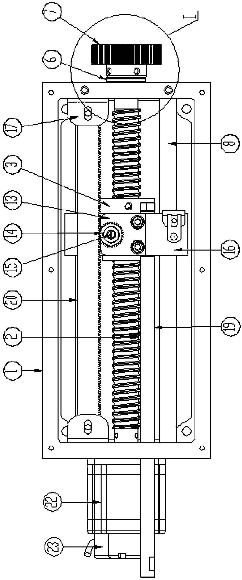
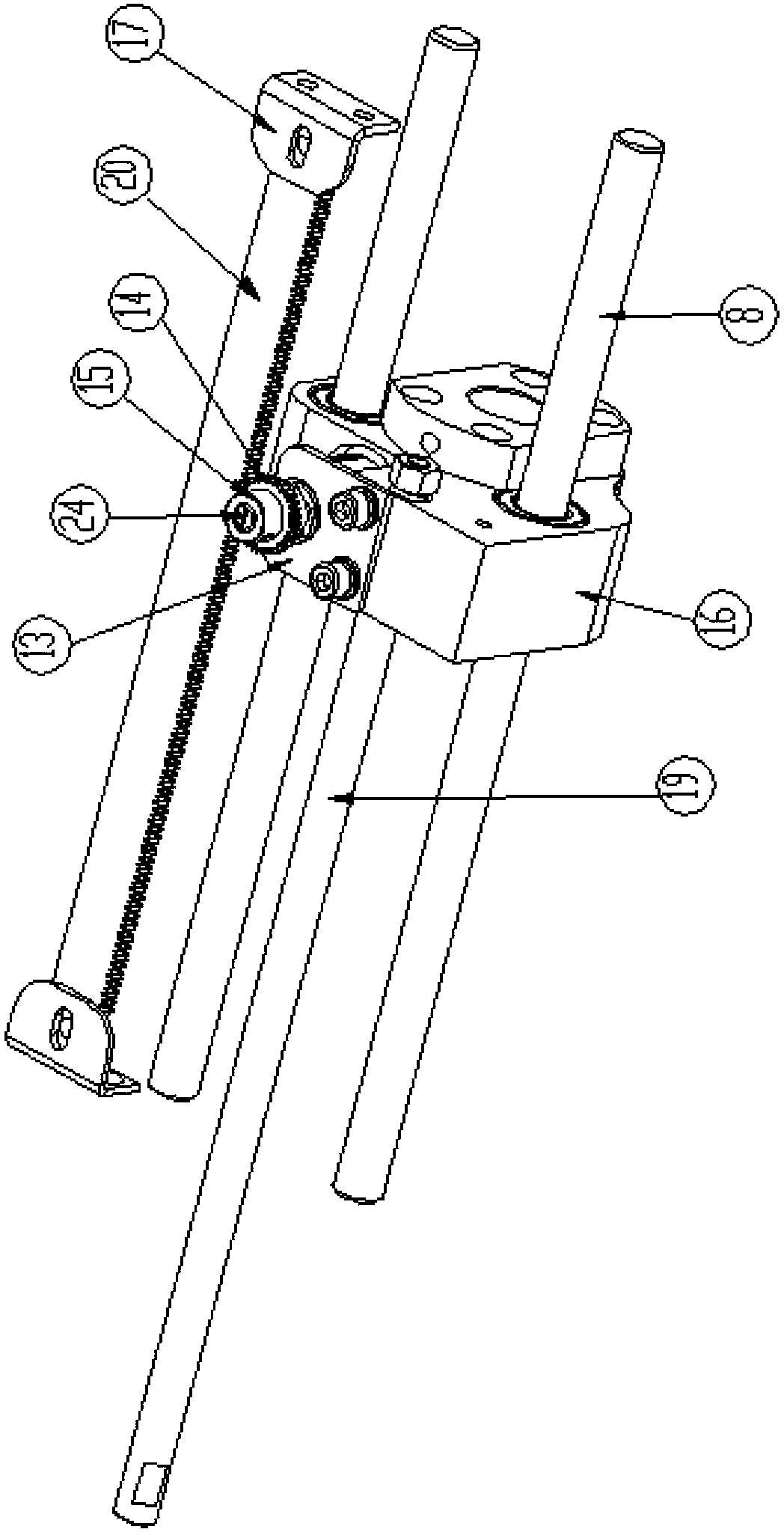
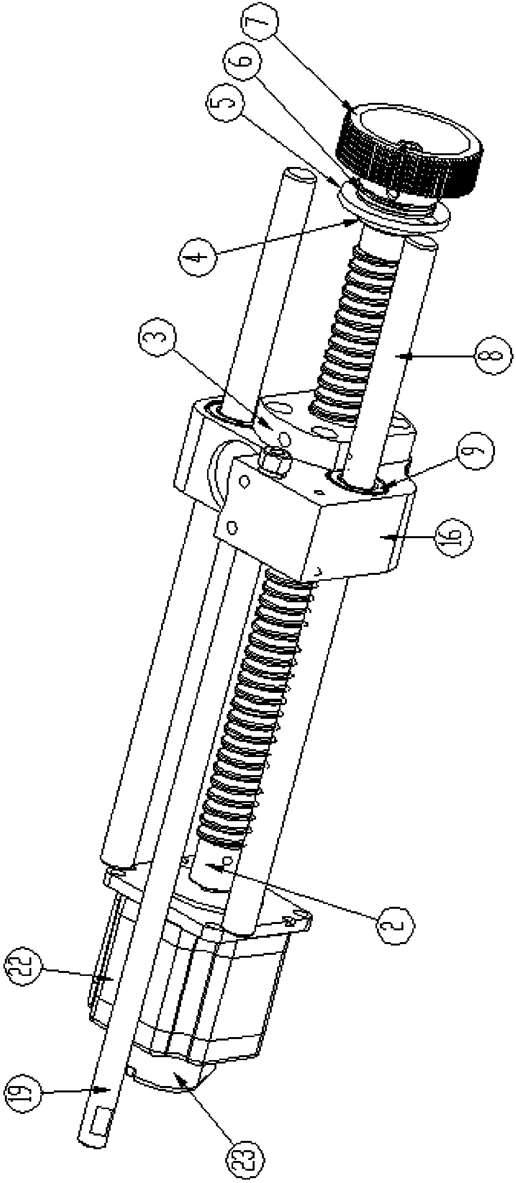
[0029] Such as Figure 1-3 As shown, the color changing device of the present invention includes a needle bar frame driving device and a needle position signal collecting device.

[0030] The present invention preferably following structure is used as needle bar holder driving device: it comprises push rod 19, driving seat 16, screw nut pair, guide rail 8 and the stepping motor 22 that drive screw rod rotates. The driving seat 16 is slidingly connected with the guide rail 8 and fixedly connected with the nut. One end of the push rod 19 is fixedly arranged on the driving seat 16, and the push rod 19 is arranged in parallel with the guide rail 8, and the other end of the push rod passes through the through hole on the casing and is fixedly connected with the needle bar frame. One end of the screw rod is fixedly connected with the box body 1 through a bearing,...


PUM


Abstract

The invention provides a color-changing device of a computer embroidery machine, aiming at solving the problems of bad quality of embroidery products caused by low marginal definition of embroidery patterns and not clear color differences of patterns when the needle position signals collected by a color-changing device generate return differences, and the device accidents happening caused by false needle position signals transmitted by a needle position signal collecting device in the prior art. The color-changing device of the computer embroidery machine comprises a needle rod frame driving device and a needle position signal collecting device; the needle rod frame driving device comprises a driving seat for driving the needle rod frame, a driving seat driving device for driving the driving seat to carry out linear reciprocal displacement and a driving seat guide rail; the needle position signal collecting device comprises a potentiometer and a potentiometer shaft driving device; the potentiometer and the driving seat perform synchronous linear reciprocal displacement; and the potentiometer shaft driving device can transform the linear displacement movement of the potentiometer into gyration movement of a potentiometer shaft. With the adoption of the structure of the color-changing device of the computer embroidery machine, not only can accurate needle position signals be provided, but aslo safe and reliable color changing processes can be guaranteed.

Description

technical field [0001] The invention relates to a computerized embroidery machine, in particular to a color changing device for a computerized embroidery machine. Background technique [0002] With the improvement of people's quality of life, strict requirements have been placed on the quality of daily necessities such as clothing, home and office, especially embroidery products, exquisite and colorful embroidery patterns, clear pattern edges, and uniform pattern luster are becoming more and more popular. favored by people. [0003] The computerized embroidery machine color changing device is a necessary mechanism serving the embroidery machine. Its function is mainly to make the color of the embroidery pattern no longer a single color. [0004] The color changing device of the computerized embroidery machine mainly includes two parts, one part is the needle bar frame driving device, and the other part is the needle position signal collecting device. A lot of needles are a...

Claims


Application Information

Patent Timeline
Patent Type & Authority Patents(China)
IPC IPC(8): D05C11/16D05C7/00
Inventor 赵尚品
Owner ZHUJI MAYA ELECTRIC APPLIANCE MACHINERY
Why Eureka
Try Eureka