
Pumping unit brake locking device

A technology of locking device and pumping unit, which is applied in the direction of mechanical equipment, mining fluid, wellbore/well parts, etc. It can solve the problems of inconvenient operation and unsafe braking, etc., so as to reduce labor intensity, reduce maintenance cost and ensure safe operation Effect

Inactive Publication Date: 2015-12-16
HENAN XINYU PETROLEUM MACHINERY MFG
View PDF6 Cites 0 Cited by
  • Summary
  • Abstract
  • Description
  • Claims
  • Application Information

AI Technical Summary

Problems solved by technology

[0003] In order to overcome the characteristics of unsafe brakes and inconvenient operation of existing beam pumping units, the present invention provides a new type of brake locking device for pumping units, which can not only brake instantly, but also lock

Method used


Image

  • Pumping unit brake locking device

Examples


Embodiment Construction

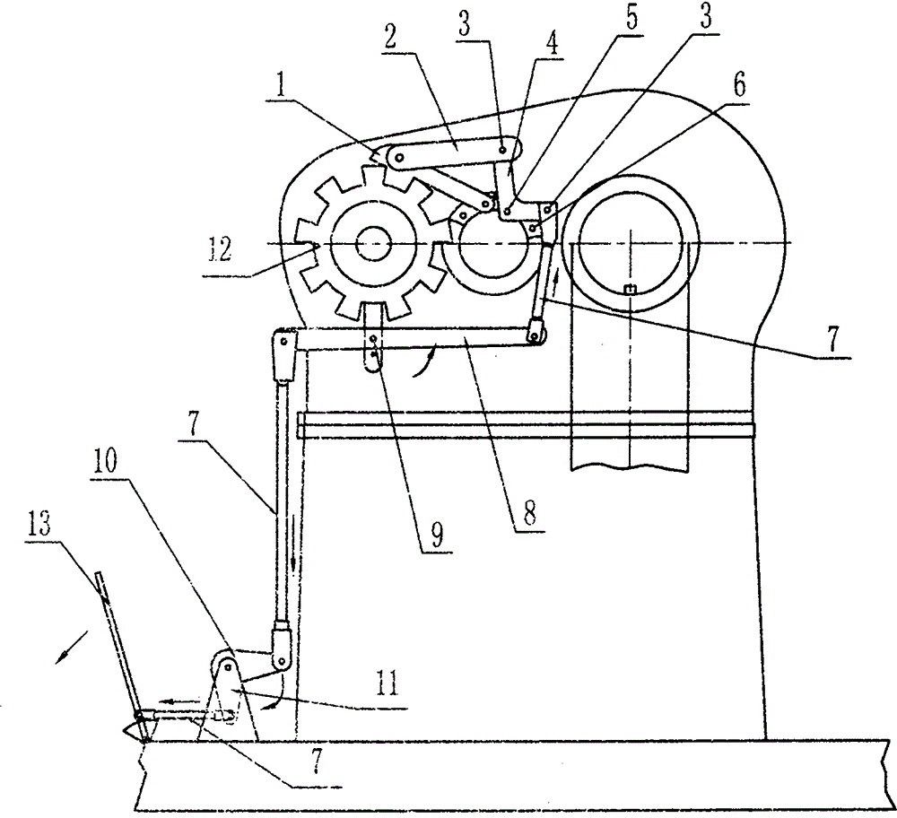
[0009] exist figure 1 In a specific embodiment, 8-12 Great Wall grooves are made along the outer edge of the brake wheel 12, and the brake claw 1 of the reduction box, the connecting plate 2, the right-angle crank arm 4, the connecting rod 7, the rocking arm 8, and the crank arm are connected with the connecting pin 3. 10, the brake connects 13. When braking, the brake handle 13 is tightened, the vertical connecting rod 7 is downward, and the left end of the rocking arm 8 is lowered and the right end is raised, the oblique connecting rod 7 is lifted up, the upper end of the right-angle crank arm 4 is inclined to the left, and the connecting plate 2 pushes the reduction box The brake claw 1 rotates to the left, and the brake claw 1 of the reduction box coincides with the wheel groove, thereby realizing braking and locking.


PUM


Abstract

The invention discloses an oil pumping unit brake locking device. On the basis of the existing hand brake, a brake locking device is added. The hand brake is used for braking, and the brake locking device is used for locking. The oil pumping unit brake locking device consists of a speed reduction box brake claw 1, a connection plate 2, a connection pin 3, a right-angle crank arm 4, a pin shaft 5, a limiting pin 6, a connection rod 7, a rocker arm 8, a rocker arm shaft 9, a crank arm 10, a crank arm seat 11, a brake wheel 12 and a brake handle 13 which are connected sequentially, wherein 8-12 tooth grooves are formed on the outer rim of the brake wheel 12, so that the speed reduction box brake claw 1 can be clamped in the grooves of the wheel timely when falling down to achieve the effects of braking and locking. By using the oil pumping unit brake locking device, safety production is achieved effectively when the oil pumping unit is stopped and overhauled. The device is operated safely and conveniently, reduces the labor intensity of workers, and shortens the maintenance time.

Description

technical field [0001] The invention relates to oil field drilling and production equipment, in particular to a pumping unit for oil production equipment. Background technique [0002] Presently known pumping units are divided into beam pumping units and beam pumping units without beams. The beam pumping unit has the advantages of simple structure, easy manufacture, high reliability, long-lasting operation, and wide adaptability to working conditions. It was widely used in the initial stage of the development of the oil production industry; , Such as low efficiency, high electricity cost, especially the brake device has potential safety hazards, inconvenient operation and other shortcomings. The original brake device can brake the output shaft of the reduction box when the hand brake is tightened, but when the pumping unit is maintained, the brake often fails to stop, so the pumping unit needs to be locked. Need two people to operate this moment, and one person tightens th...

Claims


Application Information

Patent Timeline
Patent Type & Authority Patents(China)
IPC IPC(8): F16D71/00E21B43/00
Inventor 赵磊孙学义
Owner HENAN XINYU PETROLEUM MACHINERY MFG
Learn More