Fan plate type corrugated heat exchanger

A heat exchanger and corrugated technology, applied in the field of fan plate corrugated heat exchangers, can solve the problems that fan coil heat exchangers cannot be widely used, the coil heat exchange area is small, and the coil design space is large. Installation cost, large heat exchange contact area, and low resistance

Active Publication Date: 2015-03-18
张家口越东电子科技有限公司
View PDF6 Cites 0 Cited by
  • Summary
  • Abstract
  • Description
  • Claims
  • Application Information

AI Technical Summary

Problems solved by technology

However, the coil design space of this kind of heat exchanger is large, and its heat exchange area of ​​the coil is small, the flow rate of hot water in the coil is slow, the resistance of the hot water in the coil is large, and the heat exchange efficiency of the hot air blown out is low.
Therefore, this fan coil heat exchanger cannot be widely used in the heating market

Method used


Image

  • Fan plate type corrugated heat exchanger
  • Fan plate type corrugated heat exchanger
  • Fan plate type corrugated heat exchanger

Examples


Embodiment Construction

[0031] Specific embodiments of the present invention will be described in detail below in conjunction with the accompanying drawings.

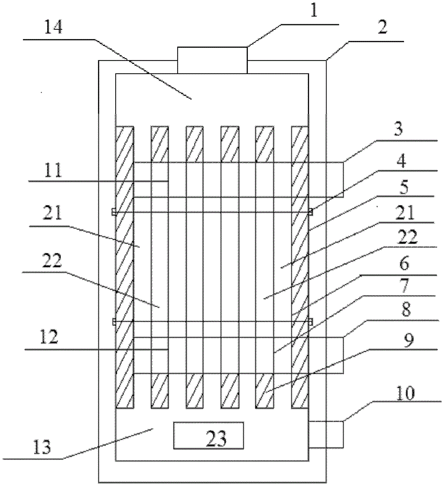
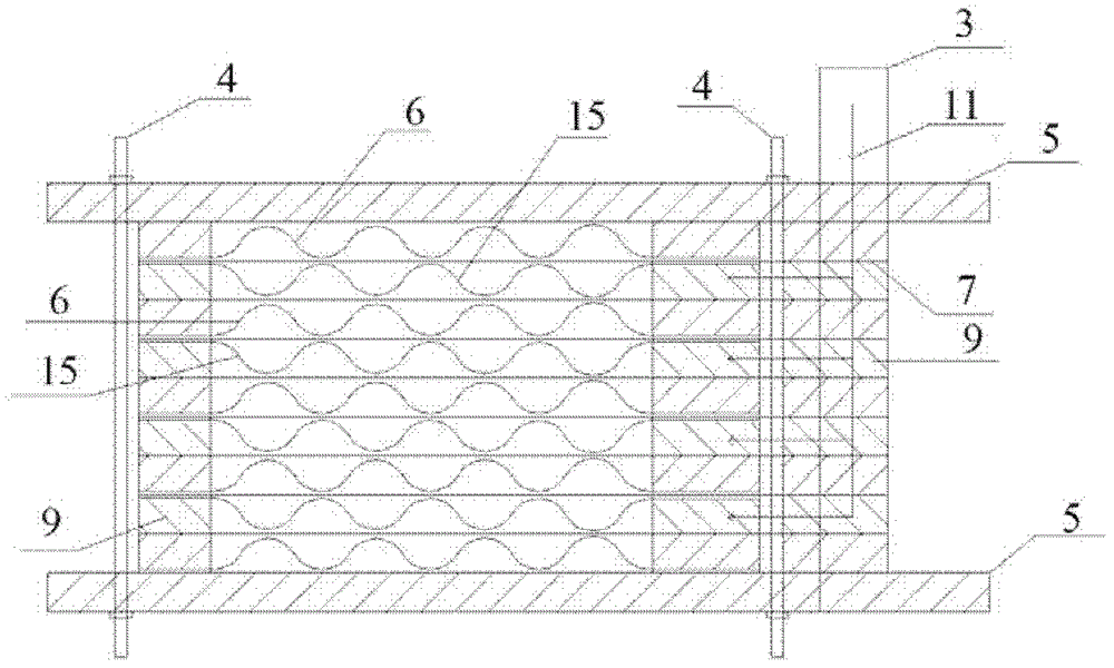
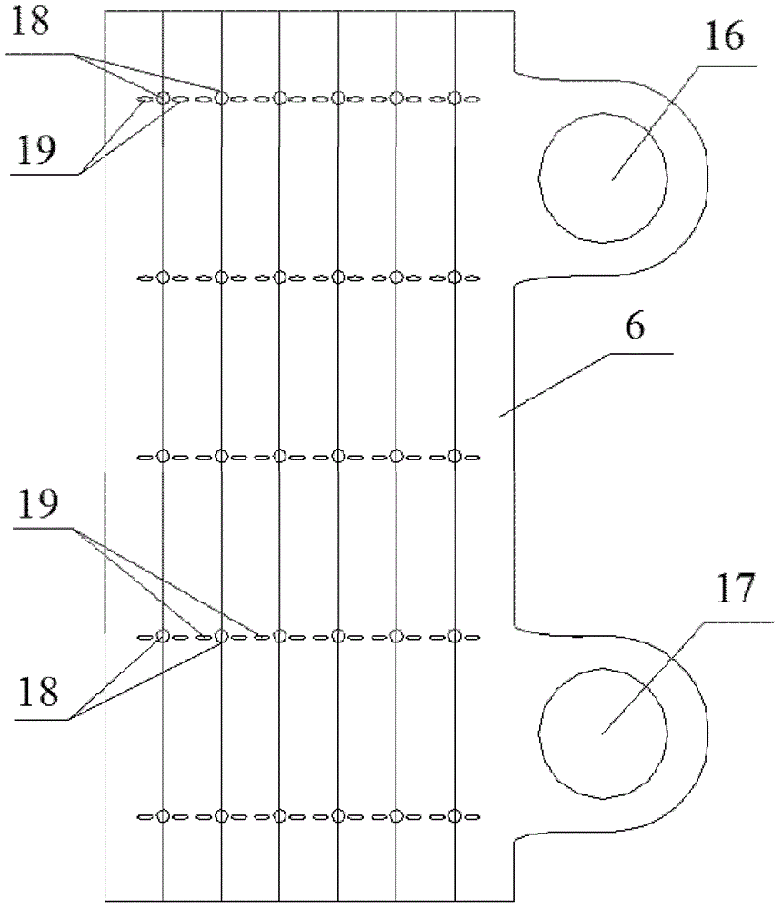
[0032] Such as figure 1 and figure 2 As shown, the fan plate type corrugated heat exchanger includes several corrugated ventilation plates 6 and several corrugated water passing plates 15, which are arranged at intervals with each other. Every two adjacent corrugated ventilating plates 6 and corrugated water passing plates 15 are separated by a separating plate 7 . All corrugated ventilating plates 6 , separating plates 7 and corrugated water passing plates 15 are fixed between two fixing plates 5 . The corresponding side of fixed plate 5, corrugated ventilation plate 6 and separating plate 7 has two protruding, consistent circular holes respectively, i.e. water inlet 16 and water outlet 17 (as image 3 , Figure 5 and Figure 6 shown in ). There is a sealing structure 9 between the corrugated ventilation plate 6 and the corrugated wate...


PUM


Abstract

The invention provides a fan plate type corrugated heat exchanger comprising at least one corrugated air ventilating plate and at least one corrugated water passing plate, which are arranged with one another at intervals, wherein the adjoining corrugated air ventilating plates and corrugated water passing plates are separated from one another by an isolation plate, and all the corrugated air ventilating plates, isolation plates and corrugated water passing plates are fixed between two fixed plates; sealed structures are respectively formed among the corrugated air ventilating plates, the corrugated water passing plates, the adjoining isolation plates or the fixed plates, so that air ways which are sealed at four sides and only allow the air to vertically pass in and out and water ways which are wholly sealed and only allow the water to pass in and out can be formed, and the air ways and the water ways are arranged with one another at intervals; and the fixed plates, the corrugated air ventilating plates, the isolation plates and one sides which correspond to seal structures among the plates are respectively provided with a convex water inlet and a convex water outlet, and each water inlet hole and each water outlet hole are communicated with one another, so that a water inlet passageway and a water outlet passageway are formed. An air inlet room of the heat exchanger further comprises at least one fan, so that the air inlet speed can be accelerated. The heat exchanger is small in design space, high in heat exchange efficiency, and quick in cooling speed, thereby being an ideal energy-saving product.

Description

technical field [0001] The invention relates to a heat exchanger, in particular to a fan plate type corrugated heat exchanger. Background technique [0002] In winter in northern my country, central heating is generally used to heat homes and offices. The heat source generated by the external boiler is connected to the heating equipment of each household through pipes. Usually, a household heat meter is connected between the heating equipment of each household and the external heat source to record the heat used by each household. Commonly used heating equipment is the original cast iron radiator and the now popular color steel radiator. This kind of heat exchange equipment in the form of radiators needs to install radiators in each room and connect them to each other through pipes, so there are many problems such as slow heat dissipation, low heat exchange efficiency, large amount of radiators, pipes and fittings, and high installation cost per household. In addition, th...

Claims


Application Information

Patent Timeline
Patent Type & Authority Patents(China)
IPC IPC(8): F28D9/00F28F3/04F28F9/22F28F9/26
Inventor 龚胜
Owner 张家口越东电子科技有限公司
Why Eureka
Try Eureka