Passive containment cooling and pressure-reducing system

A passive containment and containment cooling technology, which is applied in the field of safety systems, can solve the problems of increasing the size of the containment, increasing the construction cost, increasing the difficulty of containment design and manufacturing, and achieving the effect of improving safety

Inactive Publication Date: 2015-08-12
SHANGHAI NUCLEAR ENG RES & DESIGN INST CO LTD
View PDF8 Cites 5 Cited by
  • Summary
  • Abstract
  • Description
  • Claims
  • Application Information

AI Technical Summary

Problems solved by technology

Therefore, it is necessary to increase the size of the containment vessel, which not only increases the diff

Method used


Image

  • Passive containment cooling and pressure-reducing system
  • Passive containment cooling and pressure-reducing system
  • Passive containment cooling and pressure-reducing system

Examples


Example Embodiment

[0023] Example 1

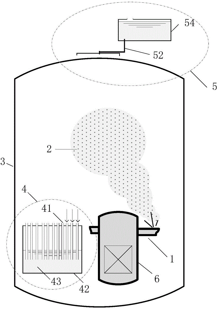
[0024] Such as figure 1 As shown, a reactor 6 is provided in the containment 3, and a passive containment cooling and pressure reduction system according to the present invention includes a containment suppression subsystem 4 and a containment cooling subsystem 5.

[0025] The containment suppression subsystem 4 includes a suppression water tank 42 arranged in the containment 3 and a discharge channel 41 passing through the top of the suppression water tank 42. Among them, the suppression water tank 42 is a closed water tank or pool, the upper part of the suppression water tank 42 is the air space, and the lower part is water 43; the discharge channel 41 is a plurality of parallel channels, one end of these channels is connected to the water in the suppression water tank 42 , The other end is connected to the atmosphere in the containment 3.

[0026] The containment cooling subsystem 5 includes an outer shell cooling pool 54 arranged above the outside of the conta...

Example Embodiment

[0028] Example 2

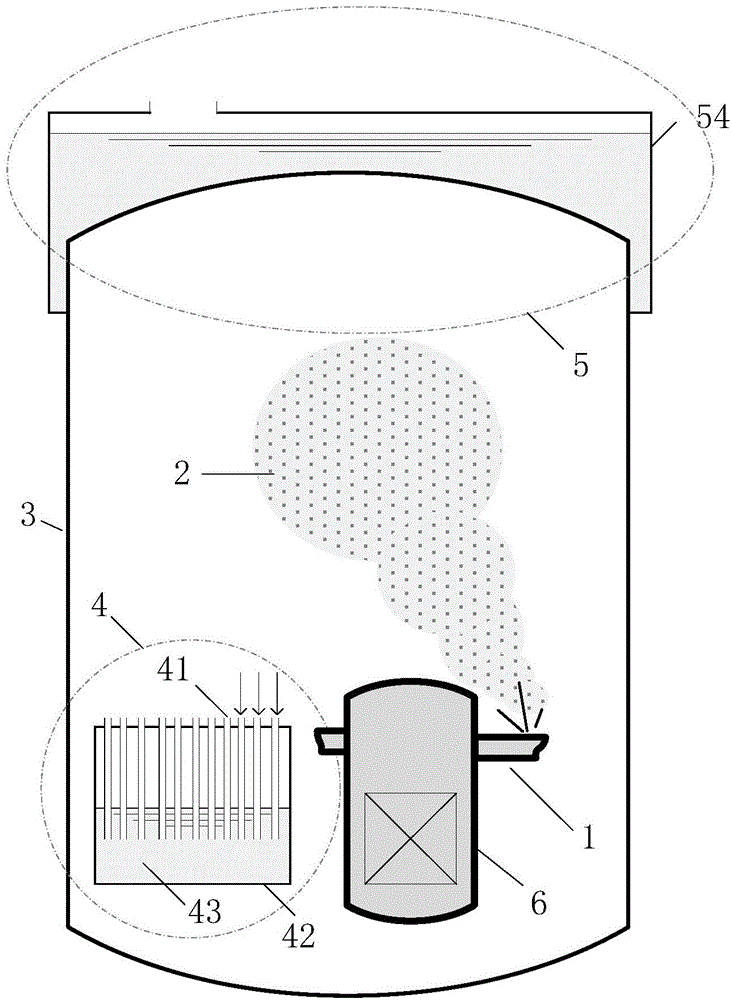
[0029] Such as figure 2 As shown, a reactor 6 is provided in the containment 3, and a passive containment cooling and pressure reduction system according to the present invention includes a containment suppression subsystem 4 and a containment cooling subsystem 5.

[0030] The containment suppression subsystem 4 includes a suppression water tank 42 arranged in the containment 3 and a discharge channel 41 passing through the top of the suppression water tank 42. Among them, the suppression water tank 42 is a closed water tank or pool, the upper part of the suppression water tank 42 is the air space, and the lower part is water 43; the discharge channel 41 is a plurality of parallel channels, one end of these channels is connected to the water in the suppression water tank 42 , The other end is connected to the atmosphere in the containment 3.

[0031] The containment cooling subsystem 5 includes a cooling pool 54 outside the containment vessel 3 and submerging the...

Example Embodiment

[0033] Example 3

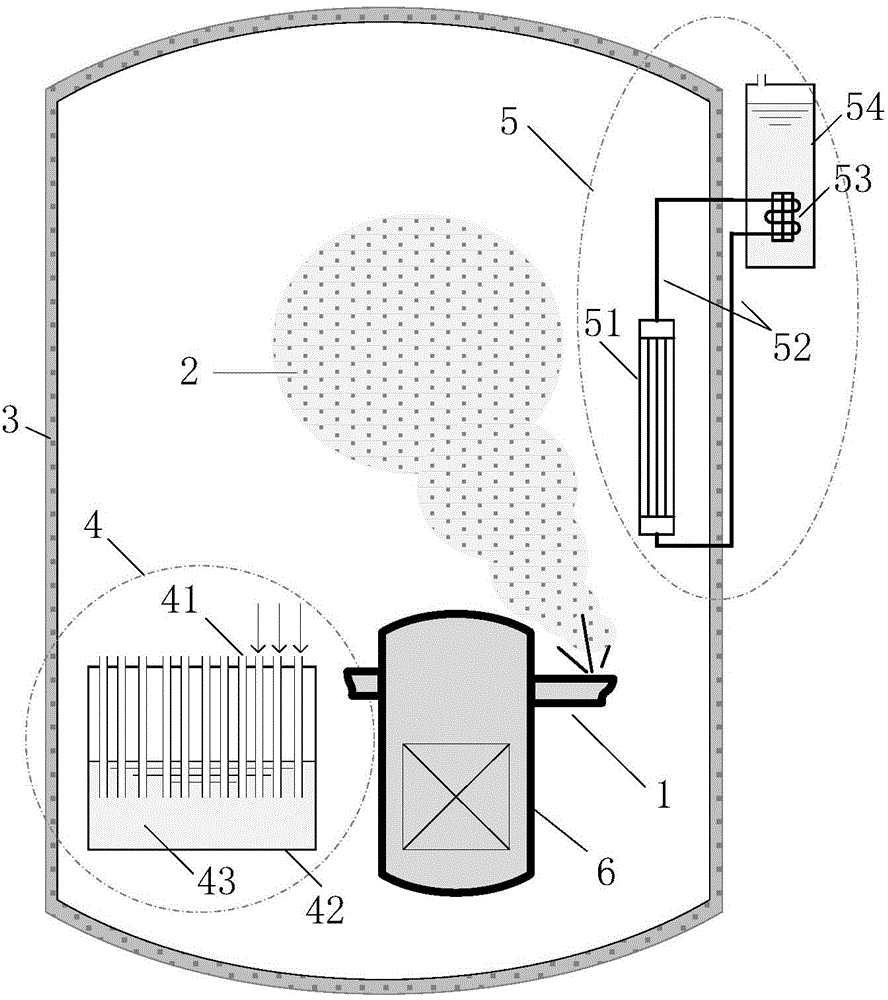
[0034] Such as image 3 As shown, a reactor 6 is provided in the containment 3, and a passive containment cooling and pressure reduction system according to the present invention includes a containment suppression subsystem 4 and a containment cooling subsystem 5.

[0035] The containment suppression subsystem 4 includes a suppression water tank 42 arranged in the containment 3 and a discharge channel 41 passing through the top of the suppression water tank 42. Among them, the suppression water tank 42 is a closed water tank or pool, the upper part of the suppression water tank 42 is the air space, and the lower part is water 43; the discharge channel 41 is a plurality of parallel channels, one end of these channels is connected to the water in the suppression water tank 42 , The other end is connected to the atmosphere in the containment 3.

[0036] The said containment cooling subsystem 5 includes an in-shell condenser 51 arranged in the containment 3, an outer-...


PUM


Abstract

The invention provides a passive containment cooling and pressure-reducing system. A reactor is arranged in the containment. The system includes a containment pressure-inhibiting sub system and a containment cooling sub system, wherein the containment pressure-inhibiting sub system includes a pressure-inhibiting water tank and a discharge channel arranged in the containment. The containment cooling sub system can be arranged in various structures. The containment cooling sub system and the containment pressure-inhibiting sub system are passive and are free from being driven by external power supplies. In the invention, by means of the passive measurement for reducing vapor amount and reducing gas temperature, the pressure in the containment is reduced, so that not only are functions of early-stage peak clipping and pressure reducing and long-time cooling and pressure reducing satisfied but also the volume of the containment is not necessary to increase, thereby reducing design size of the containment and furthermore reducing cost.

Description

technical field [0001] The invention relates to a safety system of a nuclear power plant, in particular to a passive containment cooling and depressurization system. Background technique [0002] The containment of a nuclear power plant is the last physical barrier to protect the public and the environment from radioactive releases. In the case of a breach of the main coolant system or a rupture of a steam pipeline in a nuclear power plant, a large amount of high-temperature and high-pressure steam is released into the containment. According to the ideal gas equation P=nRT / V, when the containment volume V remains constant, with the increase of the steam volume n and the gas temperature T in the containment, the pressure P in the containment rises rapidly, which will poses a serious threat to the integrity of the containment shell. [0003] In this type of accident, in order to prevent the overpressure failure of the containment, the traditional PWR nuclear power plant is e...

Claims


Application Information

Patent Timeline
IPC IPC(8): G21C15/16G21C15/18G21C9/004
CPCG21C9/004G21C15/16G21C15/18Y02E30/30
Inventor 司胜义林千廖亮张维忠
Owner SHANGHAI NUCLEAR ENG RES & DESIGN INST CO LTD
Why Eureka
Try Eureka