
Anti-rollover device used for high-speed driving maneuverability test and anti-locking test for car

A high-speed driving and maneuverability technology, which is applied to measurement devices, vehicle testing, and machine/structural component testing. problems, to achieve the effect of good force, protection and safety, and convenient use

Active Publication Date: 2014-07-09
ANHUI JIANGHUAI AUTOMOBILE GRP CORP LTD
View PDF6 Cites 0 Cited by
  • Summary
  • Abstract
  • Description
  • Claims
  • Application Information

AI Technical Summary

Problems solved by technology

[0002] At present, my country's automobile test standards are becoming more and more stringent, and more and more items are required for mandatory tests. Adhesion tests are particularly prone to accidents such as vehicle rollover or rollover, and even serious car crashes and fatalities
[0003] Under normal circumstances, the roll damping system composed of shock absorbers, stabilizer bars, rubber bushings, etc. has been considered in the design of various vehicles to give the test vehicle a certain elastic recovery moment to restore it to its original state, but this system generally only considers the vehicle Moment balance under normal driving conditions
However, when the vehicle used for a certain test project undertakes some limit test tasks, due to the excessive speed, excessive steering action or poor grip performance of one side tire, the rolling moment of the vehicle is greater than its own rolling damping coefficient. When the elastic restoring moment of , the vehicle will inevitably roll or roll over
At present, when carrying out such high-risk tests, various automobile manufacturers often adopt the method of reducing vehicle speed to avoid rollover or rollover, but in doing so, relevant test data cannot be obtained, which has brought a negative impact on the development of the whole vehicle.

Method used


Image

  • Anti-rollover device used for high-speed driving maneuverability test and anti-locking test for car
  • Anti-rollover device used for high-speed driving maneuverability test and anti-locking test for car
  • Anti-rollover device used for high-speed driving maneuverability test and anti-locking test for car

Examples


Embodiment

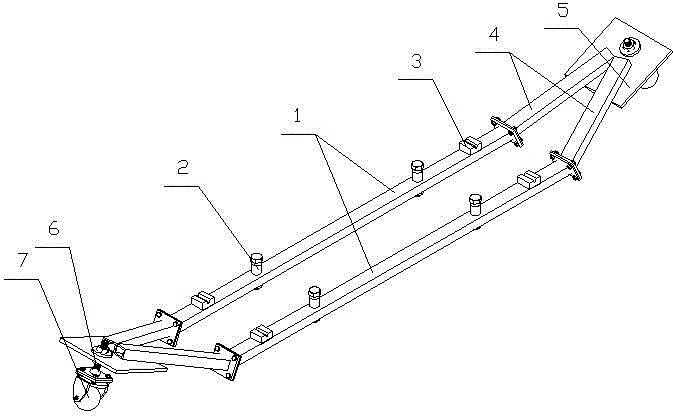
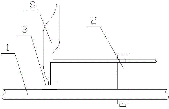
[0025] see figure 1 , figure 2 and image 3 , the anti-rollover device for high-speed car handling test and anti-lock braking test includes two parallel beams 1, the beam 1 is a hollow flat steel pipe section, the length is 1800 mm, and the distance between the two beams is 650-700 mm . Two upright fixed sleeves 2 are evenly distributed in the middle of each beam 1, and the inner diameter of the fixed sleeves 2 is 40mm;

[0026] Mounting bolts are respectively installed in each fixed sleeve 2, and pads 3 are installed on the beams 1 outside the two fixed sleeves 2 respectively. The groove is perpendicular to the beam 1. One end of the two beams 1 is connected to the two ends of the V-shaped frame 4, and the other end is connected to the two ends of another V-shaped frame 4, and the outside of the V-shaped frame 4 is tilted upwards, so that the gap between the V-shaped frame 4 and the cross beam 1 form an included angle of 160 degrees; the height of the V-shaped frame 4 i...


PUM


Abstract

The present invention involves the anti -rolling test of the high -speed driving of the car and the anti -hugging test.This device includes two parallel beams. The middle part of each beam is equipped with two fixed sleeves. Each fixed sleeve is equipped with a installation bolt.One end of the root beam is connected to the two ends of the V -shaped frame, and the other end is connected to the two ends of the other V -shaped frame, and the outer V -shaped frame is upward, so that the V -shaped frame and the beams form a angle; both ends are ends.The support board is connected to the outside of the bending of the V -shaped frame. The bottom of each support plate is installed with a universal ball through the supporting bolt.The structure of the present invention is simple. It can be easily used without changing the structure of the test vehicle, and it is convenient to disassemble. It is good for the ground with the tires as auxiliary tires and has good stability.The present invention can effectively protect the safety of test vehicles and personnel when conducting high -risk tests.

Description

technical field [0001] The invention belongs to the technical field of automobile testing, and in particular relates to an anti-rollover device for preventing vehicles and people in the vehicles in high-risk tests from being injured by rollover accidents. Background technique [0002] At present, my country's automobile test standards are becoming more and more stringent, and more and more items are required for mandatory tests. Adhesion tests, etc. are particularly prone to accidents such as vehicle rollover or even rollover, and even cause car crashes and fatalities. [0003] Under normal circumstances, the roll damping system composed of shock absorbers, stabilizer bars, rubber bushings, etc. has been considered in the design of various vehicles to give the test vehicle a certain elastic recovery moment to restore it to its original state, but this system generally only considers the vehicle Balance of torque under normal driving conditions. However, when the vehicle use...

Claims


Application Information

Patent Timeline
Patent Type & Authority Patents(China)
IPC IPC(8): G01M17/007
Inventor 丁金海孙丁柱霍修军徐清魁孙兆华王克敏马海涛刘立明
Owner ANHUI JIANGHUAI AUTOMOBILE GRP CORP LTD
Learn More