Electrooptic device, method for controlling electrooptic device, and electronic apparatus

A technology of an electro-optical device and a control method, which is applied to instruments, static indicators, etc., can solve problems such as flickering and different effective voltages, and achieve the effect of suppressing afterimages

Inactive Publication Date: 2012-08-15
SEIKO EPSON CORP
View PDF9 Cites 2 Cited by
  • Summary
  • Abstract
  • Description
  • Claims
  • Application Information

AI Technical Summary

Problems solved by technology

[0004] However, in the invention disclosed in Patent Document 1, since the voltage of the common electrode is corrected during AC driving, the effective voltage is different when a positive voltage is applied to the pixel electrode and when a negative voltage is applied, so that flicker occurs.

Method used


Image

  • Electrooptic device, method for controlling electrooptic device, and electronic apparatus
  • Electrooptic device, method for controlling electrooptic device, and electronic apparatus
  • Electrooptic device, method for controlling electrooptic device, and electronic apparatus

Examples


no. 1 Embodiment approach

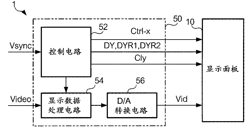
[0039] figure 1 It is a block diagram showing the configuration of the electro-optical device 1 according to one embodiment of the present invention. Such as figure 1 As shown, the electro-optical device 1 is roughly divided into a display panel 10 and a processing circuit 50 . Among them, the circuit module that controls the operation of the display panel 10, that is, the processing circuit 50 includes a control circuit 52, a display data processing circuit 54, and a D / A conversion circuit 56, and is connected to the display panel by, for example, an FPC (flexible printed circuit) substrate. 10 connections. The electro-optical device 1 is an example of a liquid crystal device that displays images using liquid crystals.

[0040] The control circuit 52 generates various control signals for controlling the display panel 10 in synchronization with a synchronization signal Vsync supplied from an external high-level device (not shown). However, these control signals will be app...

no. 2 Embodiment approach

[0091] Next, a second embodiment of the present invention will be described. The hardware configuration of the electronic device according to the second embodiment of the present invention is the same as that of the first embodiment, and the holding period of the positive voltage and the holding period of the negative voltage are different from the first embodiment. The description of the same hardware configuration as that of the first embodiment will be omitted, and the differences from the first embodiment will be described below.

[0092] In the first embodiment described above, the start pulses DYR1 and DYR2 are output, and the holding period of the positive voltage is shorter than the holding period of the negative voltage, but the holding period of the positive voltage is shorter than the holding period of the negative voltage. The method of shortening the period is not limited to the configuration of the first embodiment described above. In the present embodiment, the...

no. 3 Embodiment approach

[0096] Next, a third embodiment of the present invention will be described. The hardware configuration of the electronic device according to the third embodiment of the present invention is the same as that of the first embodiment, and the holding period of the positive voltage and the holding period of the negative voltage are different from the first embodiment. The description of the same hardware configuration as that of the first embodiment will be omitted, and the differences from the first embodiment will be described below.

[0097] In the present embodiment, in the writing triggered by the start pulse DY1, the pixel is written with a positive voltage, and in the writing triggered by the start pulse DY2, the pixel is written with a negative voltage. enter. In addition, in the present embodiment, the first set value is set to "0", and the second set value is set to "m".

[0098] According to the composition, if Figure 16 As shown, in one frame, the start pulse DY1 i...


PUM


Abstract

In writing performed at a start pulse DY1, the writing is performed with a positive-polarity voltage, and, in writing performed at a start pulse DY2, the writing is performed with a negative-polarity voltage. In writing performed at start pulses DYR1 and DYR2, the writing is performed with a voltage that turns pixels into black of minimum gradation. Since a period in which the positive-polarity voltage is retained is different from a period in which the negative-polarity voltage is retained, a direct-current component which is applied to a liquid crystal capacitor is cancelled, whereby the occurrence of burn-in is prevented.

Description

technical field [0001] The present invention relates to a technique for preventing image sticking of a display image in an electro-optical device. Background technique [0002] In a liquid crystal display device, when a direct current component acts on a liquid crystal element, the charge balance is disturbed due to the polarization of the liquid crystal, and image sticking of a displayed image occurs. Therefore, in general, liquid crystal elements are AC-driven in liquid crystal display devices. However, since a DC component may be applied to the liquid crystal even when AC driving is performed, there is an invention disclosed in Patent Document 1 as an invention for preventing image sticking. In this invention, the voltage of the common electrode opposite to the pixel electrode is corrected according to the characteristics of the display device, so as to reduce the DC component acting on the liquid crystal, thereby suppressing the generation of afterimages. [0003] Pate...

Claims


Application Information

Patent Timeline
Patent Type & Authority Applications(China)
IPC IPC(8): G09G3/20G09G3/36
CPCG09G3/3614G09G3/3677G09G3/3688G09G2310/061G09G2310/08G09G2320/0204G09G2320/0257
Inventor 水迫和久佐佐木仁
Owner SEIKO EPSON CORP
Why Eureka
Try Eureka