Non-polar safe charger circuit
A charger and circuit technology, applied in battery circuit devices, current collectors, circuit devices, etc., can solve problems such as fire, burnt batteries or chargers, and polar output terminals cannot be short-circuited.
- Summary
- Abstract
- Description
- Claims
- Application Information
AI Technical Summary
Problems solved by technology
Method used
Image


Examples
Embodiment Construction
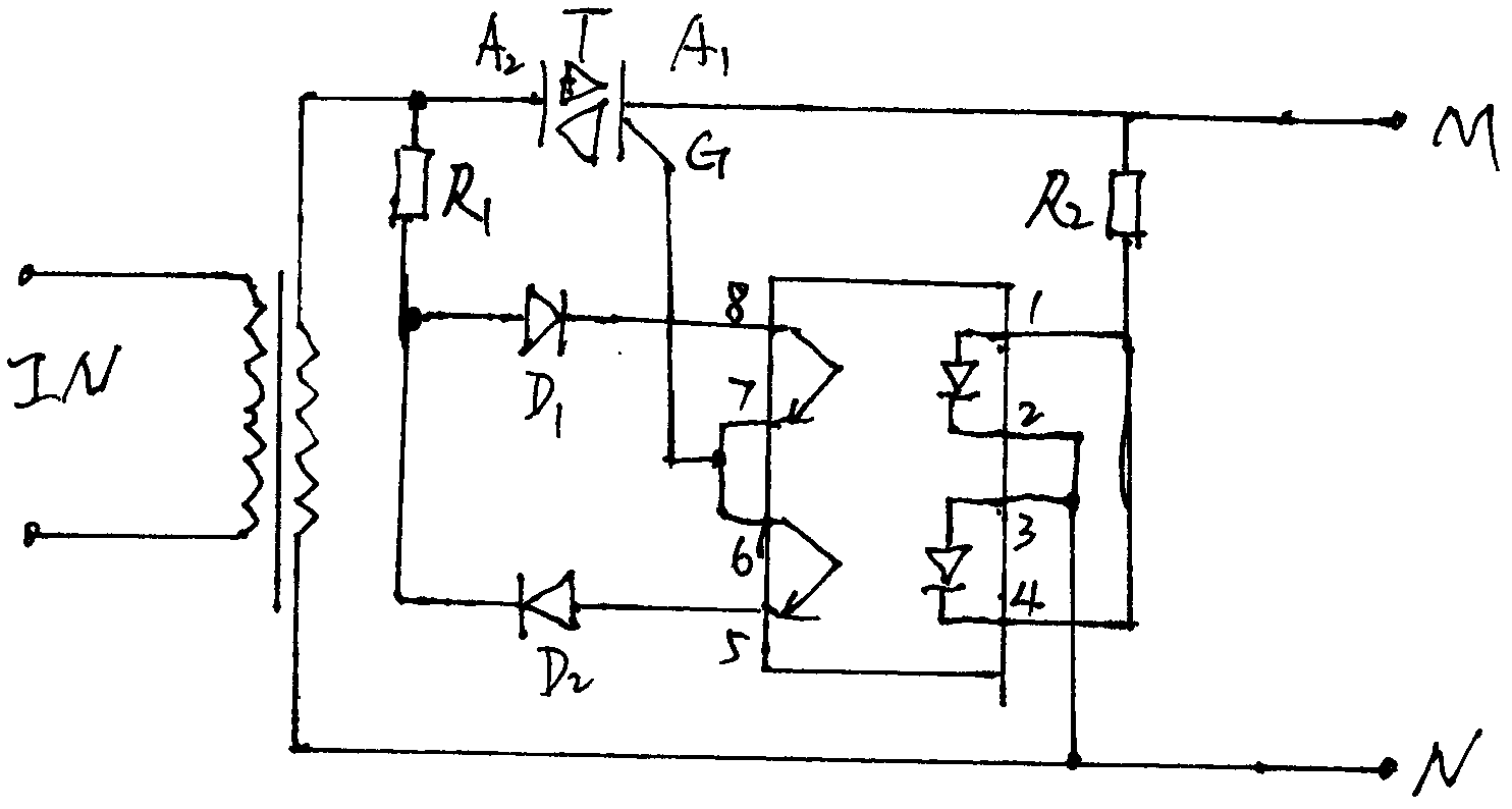
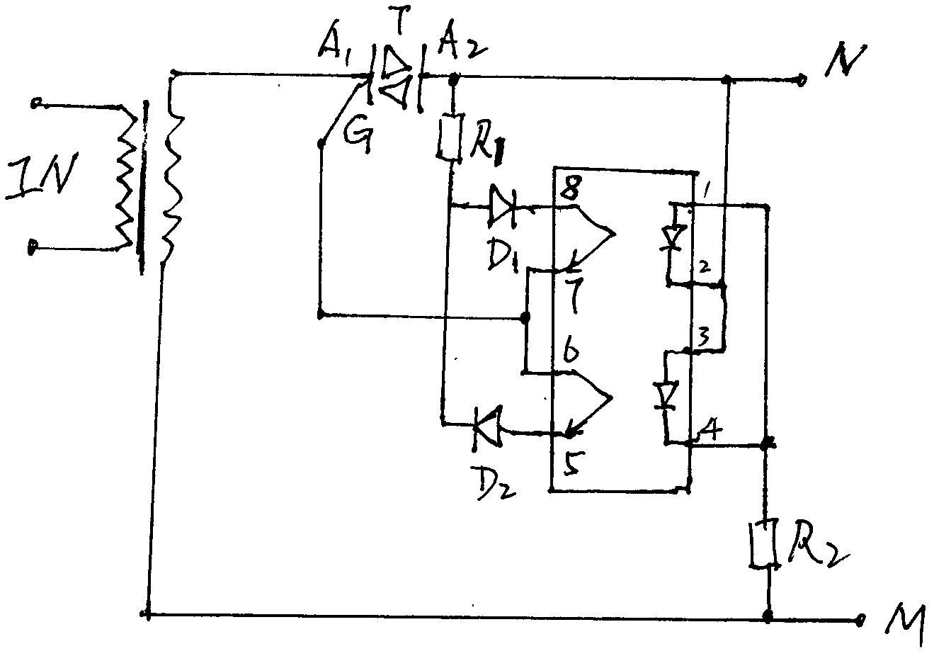
[0007] The circuit composition and working principle will be further described below in conjunction with the drawings. A bidirectional thyristor is connected in series from the output end of the power transformer B, one anode is input and the other anode is output to both ends of the polarity output. The polarity identification circuit is connected to the IC1 and 4 pins through the resistor R2, and IC2 and 3 pins. To the output terminal of the other polarity; the control electrode G is connected to IC 6, 7 (or IC5, 8), and the second anode of the thyristor is connected to the diode D1, D2 to IC8, 5 (or IC6) of opposite polarity via R1 , 7 feet), constitute a polarity automatic recognition conversion circuit. The circuit structure is simple and easy to use. Not only protects the charger in the case of a short circuit at the output terminal, but also can charge the battery correctly with any polarity. Especially suitable for charging mobile phone batteries, accumulators, etc. ...
PUM
 Abstract
Description
Claims
Application Information
 - Generate Ideas
- Intellectual Property
- Life Sciences
- Materials
- Tech Scout
- Unparalleled Data Quality
- Higher Quality Content
- 60% Fewer Hallucinations
Browse by: Latest US Patents, China's latest patents, Technical Efficacy Thesaurus, Application Domain, Technology Topic, Popular Technical Reports.
© 2025 PatSnap. All rights reserved.Legal|Privacy policy|Modern Slavery Act Transparency Statement|Sitemap|About US| Contact US: help@patsnap.com