Gas supply device

A gas supply and gas technology, applied in the direction of gas processing applications, container structure installation devices, gas processing/storage purposes, etc., can solve problems such as difficult gas pressure adjustment, gas temperature reduction, etc., to reduce energy and improve safety Effect

Active Publication Date: 2012-08-15
TAIYO NIPPON SANSO CORP
View PDF11 Cites 3 Cited by
  • Summary
  • Abstract
  • Description
  • Claims
  • Application Information

AI Technical Summary

Problems solved by technology

At this time, since the temperature of the gas decompressed by the decompression unit is lowered due to adiabatic expansion and the Joule-Thomson effect, dew condensation and frost may occur on the outer surface of the decompression unit, making it difficult to monitor the pressure of the gas. adjustment

Method used


Image

  • Gas supply device
  • Gas supply device
  • Gas supply device

Examples


Embodiment Construction

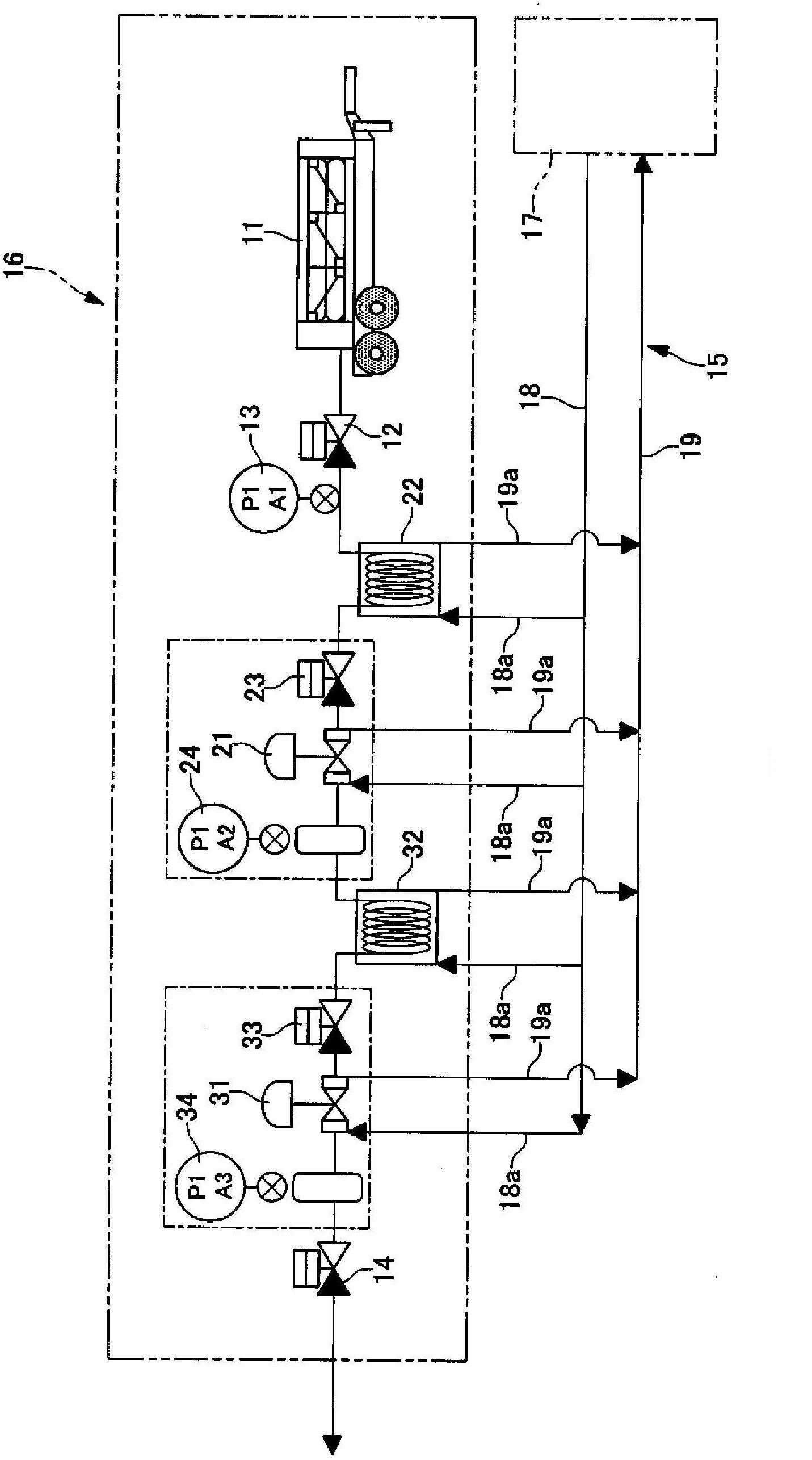
[0020] In the gas supply device shown in this embodiment, two pressure regulators 21 and 31 are provided in series as decompression means for reducing the pressure of the gas supplied from the high-pressure gas container 11 . 11 is a compressed gas supply source filled with compressed gas in a predetermined high-pressure state; and is formed so that the high-pressure gas is decompressed at a predetermined degree of decompression by the first pressure regulator 21 flowing to the upstream side of the gas. As the intermediate-pressure gas, the intermediate-pressure gas is decompressed at a predetermined decompression degree by the second pressure regulator 31 on the downstream side, and a low-pressure gas of a pressure according to a request of a supply destination is supplied. For example, in the case of supplying a compressed gas whose filling pressure is 9 MPa (absolute pressure, the same applies hereinafter) to near atmospheric pressure, after the pressure is reduced to an int...


PUM


Abstract

Provided is an economically advantageous and safe gas supply device which can stably supply compressed gas by reducing the pressure thereof. The gas supply device supplies the gas supplied from a compressed gas supply source (high-pressure gas container [11]) by reducing the pressure of said gas using a decompression means (pressure regulator [21 and 31]), wherein heat exchangers (22 and 32) for heating the aforementioned gas by exchanging the heat between the gas introduced to the decompression means and the hot water supplied from a hot-water supplying source (hot-water circulation unit [15]) are disposed on the upstream side in terms of the direction of gas flow on the decompression means, and the decompression means is provided with a hot-water flow path (53) for heating the decompression means using a portion of the hot water.

Description

technical field [0001] The present invention relates to a gas supply device, and more particularly, to a gas supply device that decompresses and supplies compressed gas. Background technique [0002] When supplying compressed gas from a 47-liter container or a large container, the compressed gas is decompressed to a specified pressure by a decompression unit such as a pressure regulator, a decompression valve, and a control valve. At this time, since the temperature of the gas decompressed by the decompression unit is lowered due to adiabatic expansion and the Joule-Thomson effect, dew and frost may form on the outer surface of the decompression unit, making it difficult to apply the gas pressure. adjustment. Therefore, a process of suppressing the reduction of the gas temperature after decompression is performed by the upstream piping (primary side piping) of the heating and decompression unit or the heating and decompression unit (for example, refer to Patent Documents 1 ...

Claims


Application Information

Patent Timeline
IPC IPC(8): F17C7/00
CPCF17C7/00F17C2205/0326F17C2205/0338F17C2223/0123F17C2223/035F17C2225/0123F17C2225/033F17C2227/0316F17C2227/0323F17C2227/0388F17C2250/043F17C2260/042F17C2270/05F28D1/0213F28D7/024F28F9/22F28F2009/226
Inventor 米田隆吉田隆
Owner TAIYO NIPPON SANSO CORP
Why Eureka
Try Eureka