Zipper slider with demountable pull tab

A zipper head and pull tab technology, applied in the field of zipper, can solve the problems of metal fatigue of shrapnel, large deformation of shrapnel, breakage, etc., and achieve the effects of avoiding metal fatigue, reducing deformation amplitude and prolonging service life.

Active Publication Date: 2014-12-17
开易(浙江)服装配件有限公司
View PDF5 Cites 1 Cited by
  • Summary
  • Abstract
  • Description
  • Claims
  • Application Information

AI Technical Summary

Problems solved by technology

Since the extension end of the shrapnel of the above-mentioned zipper slider is against the root of the pull nose, when the shrapnel is pressed, the root of the shrapnel and the extension end are pressed against each other, and the deformation of the shrapnel is relatively large, which is likely to cause metal fatigue on the shrapnel, resulting in the loss of elasticity of the shrapnel or even broken, which affects the service life of the zipper head
Therefore, it is necessary to improve the zipper puller of the existing detachable pull piece to solve the problem that its shrapnel is prone to metal fatigue, in order to prolong the service life of the zipper puller

Method used


Image

  • Zipper slider with demountable pull tab
  • Zipper slider with demountable pull tab
  • Zipper slider with demountable pull tab

Examples


Embodiment Construction

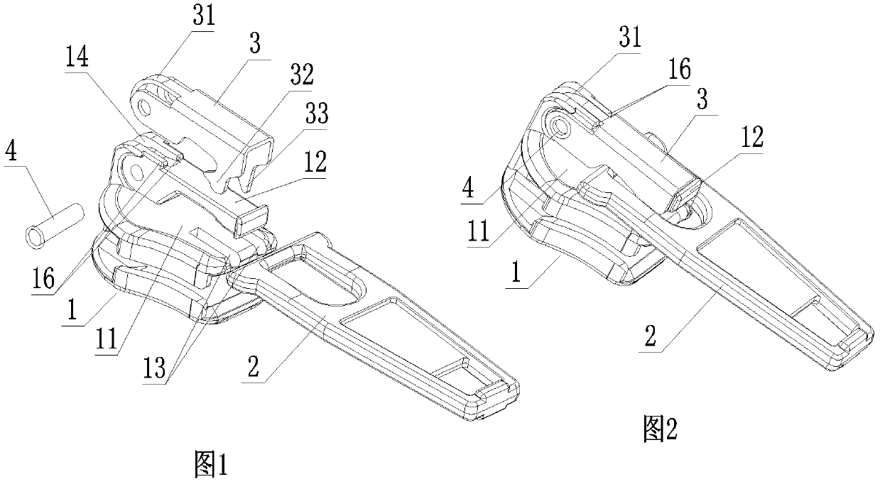
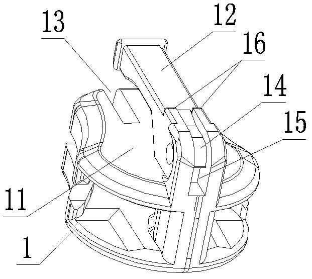
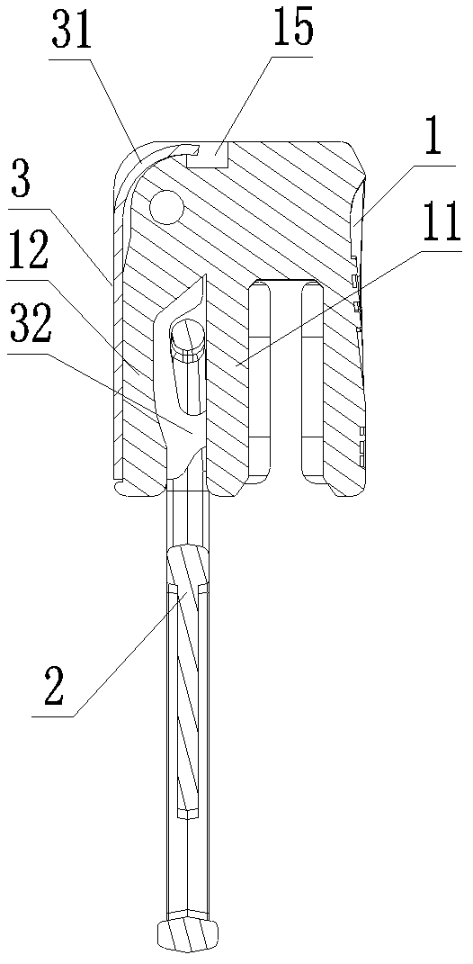
[0011] Such as Figure 1-4 As shown, a zipper puller with a detachable pull tab includes a slider body 1, a pull tab 2 and a hook 3. The upper slide plate 11 of the slider body 1 is formed with a pull nose 12, and the hook 3 is connected to the pull nose. The root of the hook 12 is hinged, and the hinged end of the horse hook 3 is formed with a shrapnel 31 that bends and extends toward the root of the pull nose 12. The two sides of the other end of the horse hook 3 are respectively formed with barbs 32 that can buckle the pull piece 2 and can be inserted. The insertion teeth 33 of the chain teeth, and the upper sliding plate 11 of the slider body 1 are respectively provided with slots 13 that can accommodate the barbs 32 and the insertion teeth 33 .

[0012] In this embodiment, the horse hook 3 is a groove-shaped cover, and the horse hook 3 is covered on the pull nose 12 . With the pin shaft 4 as the center of the circle, the inner surface of the elastic piece 31 is set as an...


PUM


Abstract

The invention discloses a zipper slider with a demountable pull tab, which comprises a zipper slider body, a pull tab and a hook. An upper slide plate of the zipper slider body is provided with a pull nose covered with the hook, and two lateral groove walls at the hinge end of the hook are hinged to the root of the pull nose. The hinge end of the hook is provided with a spring plate extending in a curved manner towards the root of the pull nose. The inner side of the hook spring plate and the groove bottom of a containing groove are both designed into involute surfaces gradually opening along the extension direction of the spring plate. The spring plate is forced to swing and deform by mutual interference between the inner side of the spring plate and the groove bottom of the containing groove, and the containing groove is provided with a recess allowing for rotation of the spring plate, so that the lengthwise extrusion deformation of the spring plate is avoided. The hook spring plate of the zipper slider compared with the existing zipper slider with a demountable pull tab has reduced deformation amplitude, the problem that metal fatigue of the spring plate is easy to occur is solved, and the service life of the zipper slider is prolonged.

Description

technical field [0001] The invention relates to the technical field of zippers, in particular to zipper sliders of zippers. Background technique [0002] As one of the ten most practical inventions for human beings in this century, zipper has been widely used in all walks of life. For the zipper puller of the traditional zipper, the pull tab is fixedly buckled on the zipper pull during the production process, and the pull tab cannot be disassembled during use. With the continuous improvement of people's pursuit of life, some manufacturers have begun to develop zippers with detachable zipper sliders to meet the different needs of people. For example, Chinese Patent No. 200920006423.9 discloses a zipper puller that can be conveniently installed with a pull tab, hinges the hook of the zipper pull with the root of the pull nose, and bends and extends a shrapnel at the hinged end of the hook, utilizing the extension end of the shrapnel and the The root of the pull nose is again...

Claims


Application Information

Patent Timeline
Patent Type & Authority Patents(China)
IPC IPC(8): A44B19/26
Inventor 李秋雷王涛
Owner 开易(浙江)服装配件有限公司
Why Eureka
Try Eureka