Circulating accelerating pipe used in annular fluidized bed reactor

A technology of fluidized bed reactor and bed reactor, which is applied in the direction of chemical instruments and methods, chemical/physical processes, etc., to achieve the effects of improving conversion rate, accelerating cycle, and adjustable working state

Inactive Publication Date: 2014-03-26
BEIJING FORESTRY UNIVERSITY
View PDF3 Cites 0 Cited by
  • Summary
  • Abstract
  • Description
  • Claims
  • Application Information

AI Technical Summary

Problems solved by technology

Although spouted beds can solve the problems of fluidized beds to some extent, so far, it is only suitable for small installations

Method used


Image

  • Circulating accelerating pipe used in annular fluidized bed reactor
  • Circulating accelerating pipe used in annular fluidized bed reactor

Examples


Embodiment Construction

[0014] The present invention will be described in detail below with reference to the drawings and embodiments.

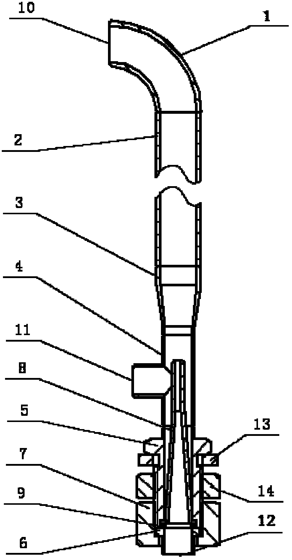
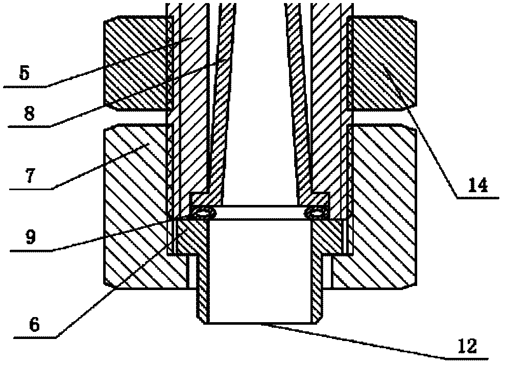
[0015] As attached figure 1 And attached figure 2 As shown, the present invention provides a circulating speed-increasing pipe used in an annular fluidized bed reactor. The circulating speed-increasing pipe includes a 90° elbow 1, a riser 2, a reducing joint 3, a three-way pipe 4, Straight pipe joint 5, connection pipe 6, first nut 7, tapered pipe 8, O-ring 9, gasket 13 and second nut 14, the peripheral equipment is a fan; the center of the straight pipe joint 5 is provided with a through hole, The lower end of the hole is machined with a sinker, and the middle circumferential surface is machined with a card slot, and the lower end circumferential surface is machined with two threads; the inner cavity of the tapered tube 8 is divided into two upper and lower sections, the upper cavity is cylindrical, and the lower section The cavity is conical, the cone angle of the ...


PUM


Abstract

The invention provides a circulating accelerating pipe used in an annular fluidized bed reactor, which comprises a 90-degree elbow pipe, a riser pipe, a reducing joint, a three-way pipe, a straight-through pipe joint, a connecting pipe, a first nut, a conical pipe, an O-shaped ring, a gasket and a second nut. The upper end of a main pipe of the three-way pipe is vertically successively connected with the reducing joint, the riser pipe and the 90-degree elbow pipe, the lower end of the main pipe of the three-way pipe is vertically successively connected with the straight-through pipe joint and the connecting pipe, the straight-through pipe joint is fixedly connected with the connecting pipe via the first nut, the conical pipe is mounted in the straight-through pipe joint, the lower end of the conical pipe is clamped in a sunken table at the lower end of a center through hole of the straight-through pipe joint, the top end of the conical pipe is higher than the axis of a side branch pipe of the three-way pipe, the O-shaped ring is disposed between the lower end surface of the conical pipe and the upper end surface of the connecting pipe, the lower end of the connecting pipe is a spraying nozzle, and the side branch pipe of the three-way pipe is an air inlet of the circulating accelerating pipe. The conical pipe is added in the circulating accelerating pipe, so that fluid circulation can be accelerated, and the conversion rate of objective products is improved.

Description

Technical field [0001] The invention relates to a speed increasing tube, in particular to a circulating speed increasing tube used in an annular fluidized bed reactor, and belongs to the technical field of fluidized bed reactors. Background technique [0002] The fluidized bed reactor is a kind of reactor that uses gas or liquid to pass through the granular solid layer to make solid particles in a suspended state, and carry out a gas-solid phase reaction process or a liquid-solid phase reaction process. When used in a gas-solid system , Also known as fluidized bed reactor. Fluidized bed technology is widely used in many industrial fields due to its unique advantages, such as efficient heat and mass transfer, uniform temperature field, large processing capacity of particles, and wide operating range. And there are still very good industrial prospects. However, the fluidized bed still has many drawbacks: 1) Due to the violent circulation and agitation of solid particles and bubbl...

Claims


Application Information

Patent Timeline
Patent Type & Authority Patents(China)
IPC IPC(8): B01J8/24
Inventor 司慧王霄常建民任学勇
Owner BEIJING FORESTRY UNIVERSITY
Why Eureka
Try Eureka