Multi-level supersonic speed cyclone separator

A cyclone separator and supersonic technology, applied in cyclone devices, devices whose axial direction of cyclone remains unchanged, etc., can solve the problems of low gas-liquid separation efficiency and separation purity, and improve separation efficiency and separation purity. , the effect of reducing energy loss

Inactive Publication Date: 2012-08-22
SHENZHEN LK SCI&TECH
View PDF7 Cites 7 Cited by
  • Summary
  • Abstract
  • Description
  • Claims
  • Application Information

AI Technical Summary

Problems solved by technology

[0008] The purpose of the present invention is to provide a multi-stage supersonic cyclone separator, which solves the problem of low separation efficiency and separation purity of gas and liquid in the existing supersonic cyclone separator

Method used


Image

  • Multi-level supersonic speed cyclone separator
  • Multi-level supersonic speed cyclone separator
  • Multi-level supersonic speed cyclone separator

Examples


Embodiment 1

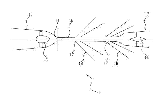
[0021] Such as figure 2 As shown, the multi-stage supersonic cyclone separator 1 provided by the first embodiment of the present invention includes a contraction tube 11, a supersonic condenser tube 12, and a diffuser tube 13 that are coaxially connected from left to right. The cross section of the contraction tube 11 It gradually decreases from left to right and shrinks to the middle into a narrow throat 14. The supersonic condenser tube 12 extends from the narrow throat 14 from left to right and the cross section gradually becomes larger. The cross section of the diffuser tube 13 gradually changes from left to right Large, the shrink tube 11 is provided with a rotating mechanism 15, the diffuser tube 13 is provided with a guide vane 16, and the supersonic condenser tube 12 is provided with at least two separation outlets 17 from left to right (that is, on the supersonic condenser tube 12). A plurality of separation outlets 17 before and after are provided, and the separation ...

Embodiment 2

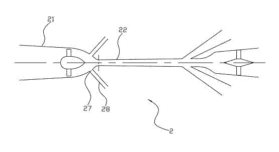
[0030] Such as image 3 As shown, the multi-stage supersonic cyclone separator 2 provided in the second embodiment of the present invention is approximately the same as the multi-stage supersonic cyclone separator 1 provided in the first embodiment. The difference is: The shrink tube 21 of the supersonic cyclone separator is also provided with at least one separation outlet 27, and the separation outlet 27 is also connected to a separation pipe 28. By providing at least one separation outlet 27 in the shrink tube 21, the liquid and solid impurities in the high-pressure gas that has not reached the speed of sound in the receiving tube 21 will be discharged from the separation outlet 27 on the shrink tube 21, and these liquid and solid impurities do not need to follow. The high-speed air flow is discharged from the separation outlet 27 on the supersonic condenser tube 22, which further reduces the energy loss of the high-speed air flow, thereby promoting the realization of higher...


PUM


Abstract

The invention discloses a multi-level supersonic speed cyclone separator. The multi-level supersonic speed cyclone separator comprises a retracting pipe, a supersonic speed condensation pipe and a pressure diffusing pipe which are coaxially communicated from left to right sequentially, wherein the cross section of the retracting pipe is gradually reduced from left to right and is shrunk into a narrow throat from the middle; the supersonic speed condensation pipe is extended from left to right from the narrow throat; the cross section of the supersonic speed condensation pipe is gradually increased from left to right; the cross section of the pressure diffusing pipe is gradually increased from left to right; a rotating mechanism is arranged in the retracting pipe; a flow guide sheet is arranged in the pressure diffusing pipe; and at least two separating outlets are sequentially formed in the supersonic speed condensation pipe from left to right and are respectively connected with separating pipes. The at least two separating outlets are sequentially formed in the supersonic speed condensation pipe from left to right, the separating outlet in the front half section of the supersonic speed condensation pipe is used for separating out a fluid with relatively high boiling point, and the separating outlet in the rear half section of the supersonic speed condensation pipe is used for separating out the fluid with relatively low boiling point, so that the energy loss of high-speed air flow is reduced, and the separation efficiency and the separation purity of gas and liquid are improved.

Description

Technical field [0001] The invention belongs to the field of low-temperature refrigeration equipment, and particularly relates to a multi-stage supersonic cyclone separator. Background technique [0002] See figure 1 , figure 1 Shown is a schematic diagram of a natural gas supersonic cyclone separator in the prior art. The supersonic cyclone separator includes a shrink tube 91, a supersonic condenser 92, a diffuser tube 93, and a shrink tube 91 that are coaxially connected from left to right. The cross section of the tube gradually decreases from left to right and shrinks to the middle into a narrow throat 94. The supersonic condenser tube 92 extends from the narrow throat 94 to the right and the cross section gradually becomes larger. The section of the diffuser tube 93 gradually becomes larger from left to right. , The shrink tube 91 is provided with a rotating mechanism 95, the diffuser tube 93 is provided with a baffle 96, the end of the supersonic condenser tube 92 (near the...

Claims


Application Information

Patent Timeline
Patent Type & Authority Applications(China)
IPC IPC(8): B04C3/02
Inventor 邢小月方思睿杜岳
Owner SHENZHEN LK SCI&TECH
Why Eureka
Try Eureka