Vacuum die casting mould

A vacuum die-casting and mold technology, applied in the field of die-casting molds, can solve the problems of difficulty in reducing, low pumping rate, and high vacuum degree, and achieves increased pumping volume and pumping rate, improved mechanical properties, and good sealing performance. Effect

Active Publication Date: 2012-08-22
TSINGHUA UNIV
View PDF5 Cites 30 Cited by
  • Summary
  • Abstract
  • Description
  • Claims
  • Application Information

AI Technical Summary

Problems solved by technology

However, the current vacuum die-casting technology generally has the disadvantages of insufficient pumping capacity, and it is difficult to achieve a high degree of vacuum within a specified time.
There are two main reasons for this phenomenon: 1. The vacuum pumping capacity of the die-casting vacuum machine is limited, and the pumping rate is low
2. The sealing performance of the die-casting mold itself is not perfect, and there is a large amount of gas leakage under high vacuum
In the current stage of vacuum die-casting production, most people only use a simple method of adding a sealing ring to seal the ejector pin hole of the die-casting mold. This method can only maintain the vacuum pressure of the die-casting mold cavity at about 20kPa, and it is difficult to further reduce it. , unable to reach the industry-recognized high vacuum level below 5kPa

Method used


Image

  • Vacuum die casting mould
  • Vacuum die casting mould

Examples


Embodiment Construction

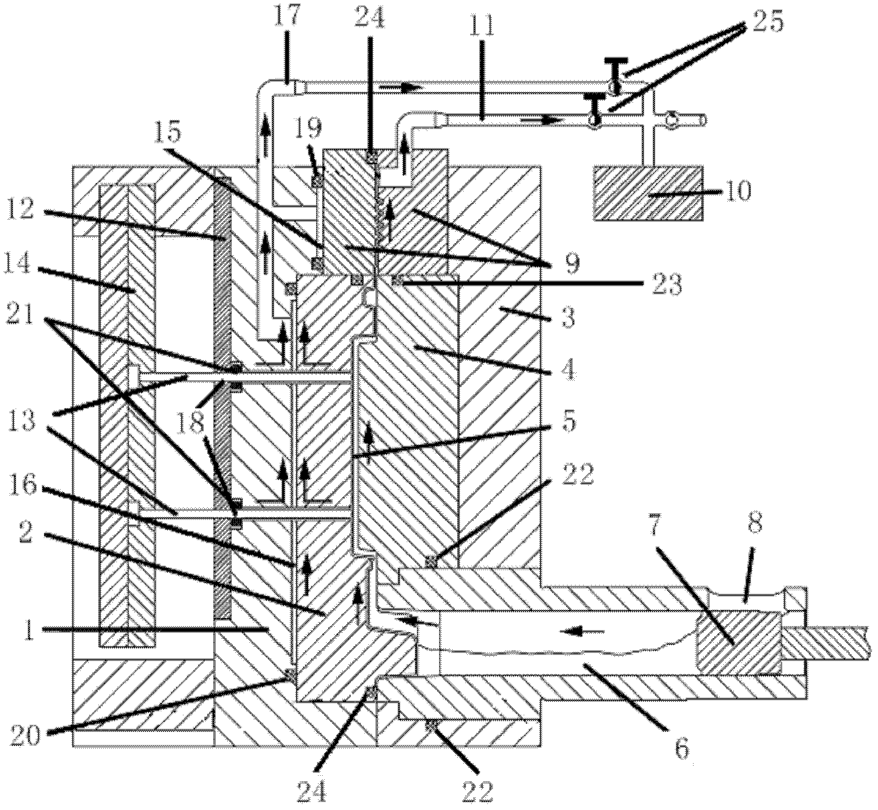
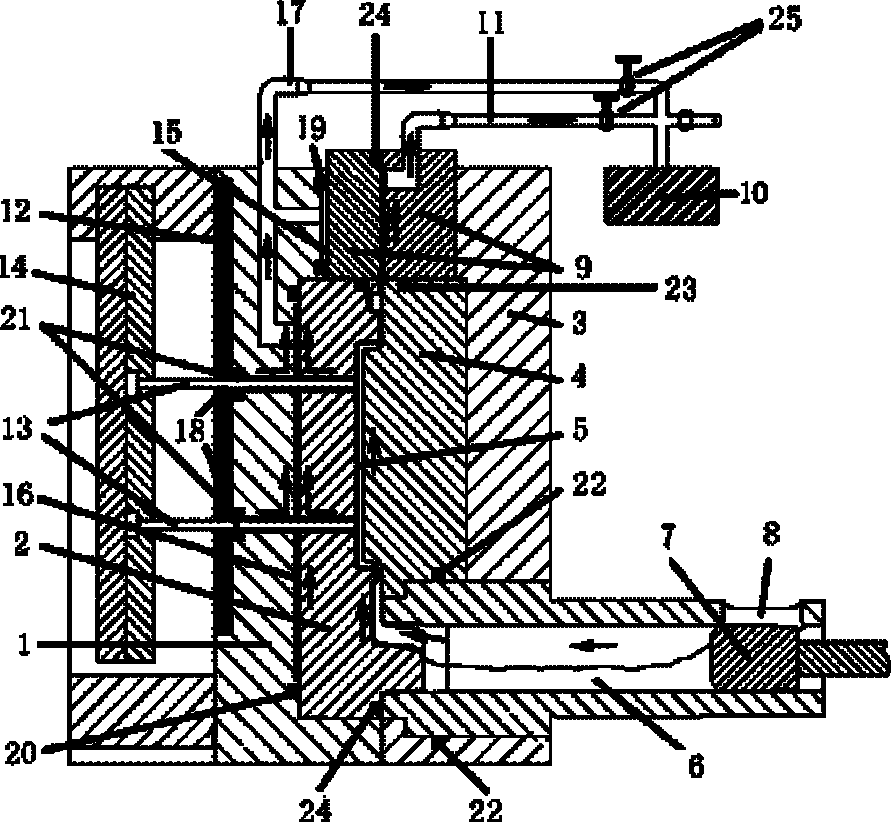
[0012] The present invention will be described in detail below in conjunction with the accompanying drawings and embodiments.

[0013] Such as figure 1 As shown, the traditional vacuum die-casting mold includes a movable mold frame 1, a movable lining mold 2 is arranged in the movable mold frame 1, a static mold frame 3 is arranged opposite to the movable mold frame 1, and a static lining mold 4 is arranged in the static mold frame 3 A casting cavity 5 is formed between the dynamic lining mold 2 and the static lining mold 4, the feed end of the casting cavity 5 is connected to the discharge end of a pressure chamber 6, and the discharge end of the pressure chamber 6 is located between the static lining mold 4 and the static lining mold 4. In the static mold frame 3, the feeding end of the pressure chamber 6 extends out of the static mold frame 3, a sealing punch 7 is arranged in the axial direction of the feeding end of the pressure chamber, and a sprue 8 is arranged in the ra...


PUM


Abstract

The invention relates to a vacuum die casting mould, which comprises a movable mould area and a static mould area. The movable mould area comprises a movable mould frame, a movable lining mould, a press plate and a top cover with a top rod. The static mould area comprises a static mould frame, a static lining mould and a press chamber. An air discharge valve is arranged at the top of the movable lining mould and the static lining mould and communicated with an external vacuum machine through air discharge pipelines. A gap is respectively retained between the movable mould frame and the air discharge valve and between the movable mould frame and the movable lining mould, and two rows of air cavities are formed through sealing elements and are communicated with the external vacuum machine through the air discharge pipelines. A sealing element is arranged on the inner side of a top rod hole of each top rod contacted with the press plate. Sealing elements are arranged between the static lining mould and the static mould frame and the outer circle of the material outlet end of the press chamber. A sealing element is respectively arranged between the top of the movable lining area and the bottom of the air discharge valve and between the top of the static lining mould and the bottom of the air discharge valve. A sealing element is arranged at the mould assembly position of the movable mould area and the static mould area. The vacuum die casting mould is capable of being used for die casting process production in high vacuum, and vacuum pressure of a cast piece cavity can be reduced to below 5kPa to achieve high vacuum level.

Description

technical field [0001] The invention relates to a die-casting mold, in particular to a vacuum die-casting die used in high-vacuum die-casting process. Background technique [0002] The existing die-casting technology usually vacuumizes the mold cavity before the die-casting machine mold is closed and filled with molten metal, so as to reduce porosity defects and improve casting quality. However, the current vacuum die-casting technology generally has the disadvantage of insufficient pumping capacity, and it is difficult to achieve a high degree of vacuum within a specified time. There are two main reasons for this phenomenon: 1. The pumping capacity of the die-casting vacuum machine is limited, and the pumping rate is low. 2. The sealing performance of the die-casting mold itself is not perfect, and there is a large amount of gas leakage under high vacuum. For the latter, the sealing performance of the die-casting mold can be improved by improving the sealing structure in ...

Claims


Application Information

Patent Timeline
Patent Type & Authority Applications(China)
IPC IPC(8): B22D17/14B22D17/22
Inventor 熊守美胡泊
Owner TSINGHUA UNIV
Why Eureka
Try Eureka