
Steel ladle capping device

A ladle and rotating arm technology, applied in metal processing equipment, casting melt container, casting equipment, etc., can solve problems such as decoupling, potential safety hazards, decoupling of the ladle cover, etc., to achieve easy operation, prevent decoupling of the hanging shaft, and maintain movement consistent effect

Active Publication Date: 2012-08-22
DALIAN HUARUI HEAVY IND GRP CO LTD
View PDF6 Cites 8 Cited by
  • Summary
  • Abstract
  • Description
  • Claims
  • Application Information

AI Technical Summary

Problems solved by technology

During the movement, there will be actions such as starting and stopping, and the ladle cover will swing on the hook due to inertia, and there is a danger of decoupling
At the same time, some projects require no gaps when lifting and lowering the cover, which requires the ladle cover to be seated directly on the ladle. If there is a slight error in the downward movement of the ladle cover arm, the ladle cover will also be in danger of decoupling, posing a safety hazard

Method used


Image

  • Steel ladle capping device
  • Steel ladle capping device
  • Steel ladle capping device

Examples


Embodiment Construction

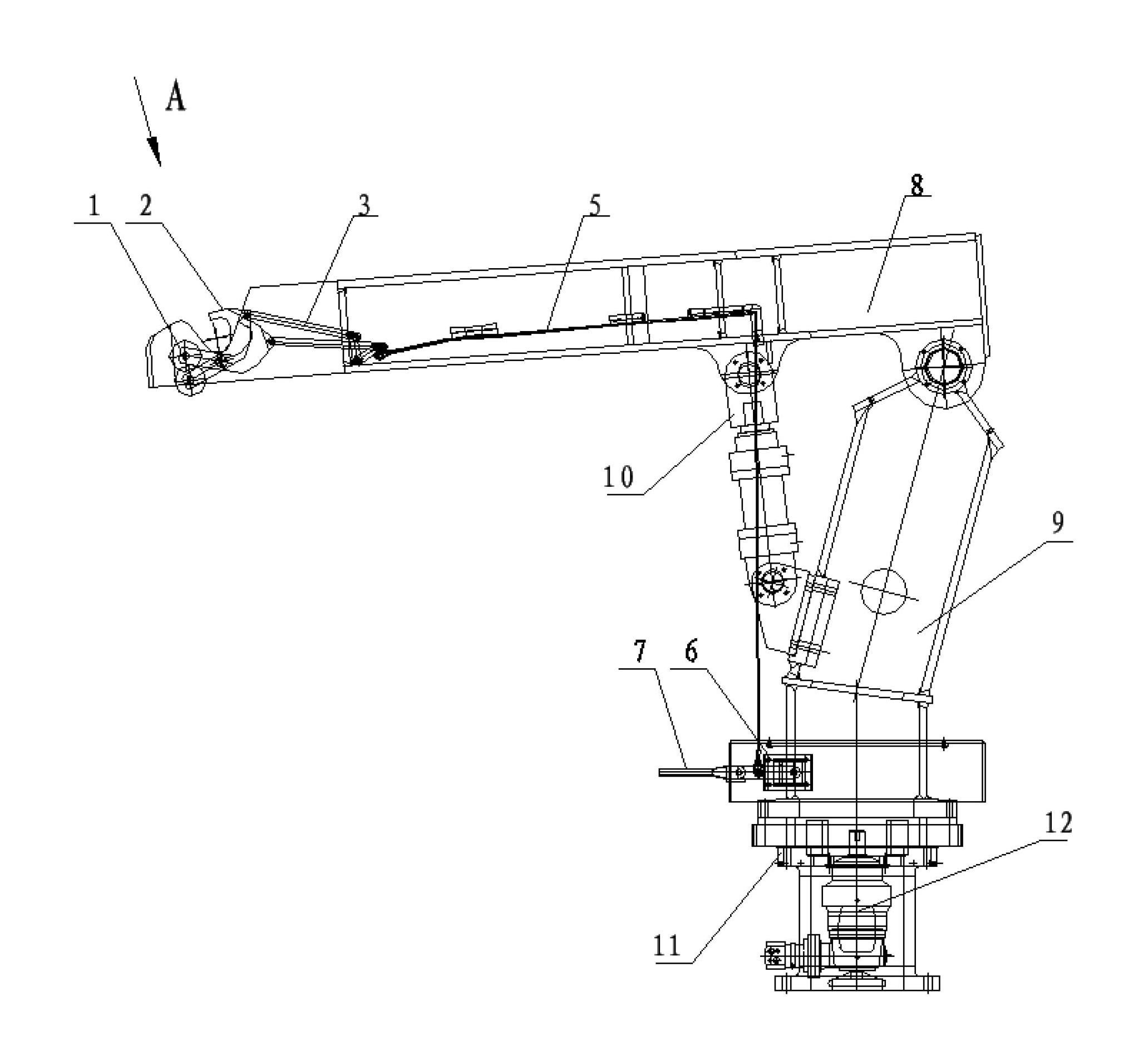
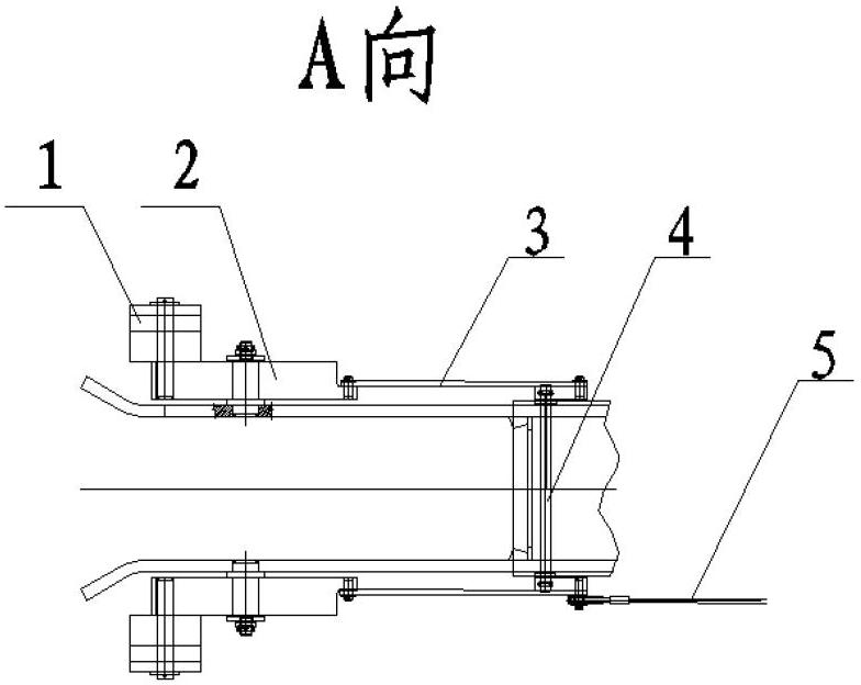
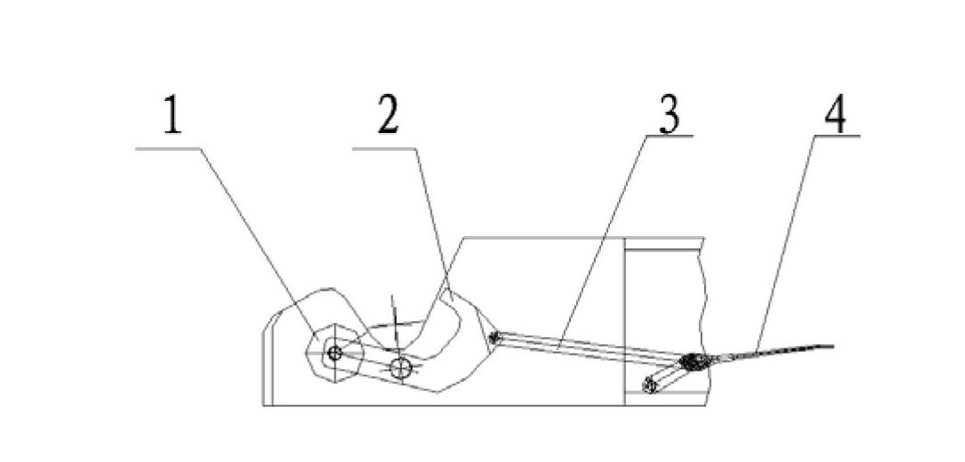
[0020] The present invention will be further described below in conjunction with the accompanying drawings. like Figure 1-2 As shown, a ladle capping device includes a rotating arm 8, a rotating column 9, a column 11, a lifting cylinder 10 and a rotary motor 12. The front end of the rotating arm 8 has a hook, and its rear end is connected to the upper end of the rotating column 9. Connection, the middle position realizes the lifting function by connecting the lower part of the lifting cylinder 10 with the rotating column 9, the lower end of the rotating column 9 is connected with the upper section of the column 11, and realizes the turning function through the rotary motor 12, and the lower end of the column 11 is installed on the rotary platform The ladle capping device also includes a counterweight 1, a locking hook 2, a connecting rod 3, a connecting shaft 4, a steel wire rope 5, a support seat 6 and a handle 7, and both sides of the hook at the front end of the rotating a...


PUM


Abstract

The invention discloses a steel ladle capping device which comprises a rotary arm, a rotary column, a column, a lifting oil cylinder and a rotary motor, and further comprises counter weights, locking hooks, connecting rods, a connecting shaft, a steel wire rope, a supporting seat and a handle, wherein both the two sides of lifting hooks at the front end of the rotary arm are provided with the counter weights, the locking hooks and the connecting rods, and the connecting rods at the two sides of the lifting hooks are connected with each other through the connecting shaft; and the steel wire rope is installed at one side of the rotary arm, one end of the steel wire rope is connected with the connecting rod, the other end of the steel wire rope passes by a fixed pipe at the side surface of the rotary arm, is turned and then tied at the middle position of the handle, and the handle is installed on the supporting seat of the lower part of the rotary column. Because the steel ladle capping device closes a lifting hook opening through the locking hooks, a relatively closed space is formed, a hanger shaft is prevented from unhooking, so the potential safety hazards of the equipment can besolved. The steel ladle capping device adopts a connecting rod mechanism as a locking device, and the steel wire rope is pulled through a lever principle, thus ensuring the structure of the mechanismto be simple, convenient to use and easy to operate.

Description

technical field [0001] The invention relates to a steelmaking equipment, in particular to a ladle capping device. Background technique [0002] In steelmaking equipment, the ladle capping device is located on the ladle turret. Existing ladle capping device mainly is made up of rotating arm, rotating column, column, lifting oil cylinder and rotary motor. The hook on the rotating arm lifts the ladle cover, and realizes the functions of lifting and turning through the action of the lifting cylinder and the slewing motor, and then realizes the function of "covering" the ladle. The ladle capping device is located on the casting platform, responsible for "capping" the molten steel from smelting and the molten steel in the process of heat preservation, and the movement is frequent. [0003] The hook of the existing ladle capping device is an open arc, which is used to accept the suspension shaft of the ladle cap. When the molten steel in the ladle needs to be kept warm, the ladl...

Claims


Application Information

Patent Timeline
Patent Type & Authority Applications(China)
IPC IPC(8): B22D41/00
Inventor 高玉华刘金
Owner DALIAN HUARUI HEAVY IND GRP CO LTD
Learn More