Elevator with floor heighting adjusting mechanism

A height adjustment mechanism and elevator technology, applied in the field of elevators, can solve problems such as the height of the elevator car, and achieve the effect of suppressing the height dimension, reducing the distance, and avoiding the increase of the space of the elevator passage

Inactive Publication Date: 2015-07-01
HITACHI LTD
View PDF6 Cites 0 Cited by
  • Summary
  • Abstract
  • Description
  • Claims
  • Application Information

AI Technical Summary

Problems solved by technology

In this case, if the existing technology is used, the height of the elevator cars will become higher, and it may be difficult to make the elevator cars stop adjacent to each other at a distance between the cars when it is necessary to ensure a safe distance between the cars. on several floors linked together

Method used


Image

  • Elevator with floor heighting adjusting mechanism
  • Elevator with floor heighting adjusting mechanism
  • Elevator with floor heighting adjusting mechanism

Examples


no. 1 example

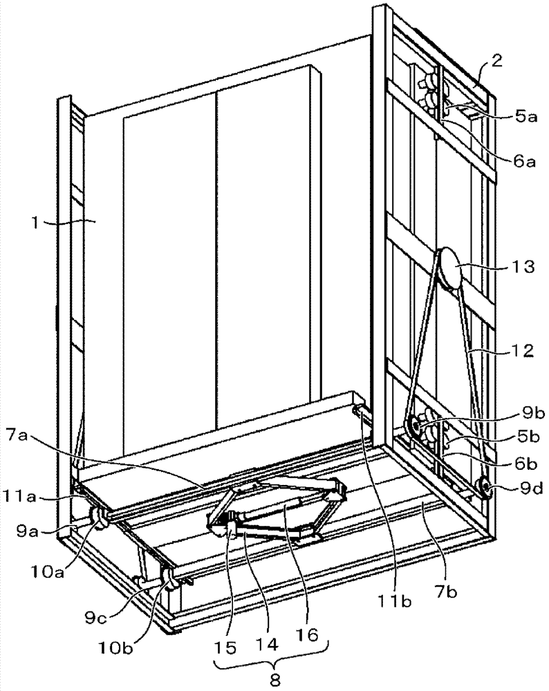
[0046] figure 1 is a perspective view of an elevator car. The elevator car of this embodiment is composed of an inner car 1 and an outer frame 2 . An unshown elevator door opening and closing motor and a control panel 4 for controlling power supply in the car, floor display, and elevator door opening and closing control are provided on the upper portion of the inner car 1 . The inner car 1 has inner car guide rollers 5a, 5b at the upper and lower portions of the left and right sides. The outer frame 2 has inner car guide rails 6a, 6b at the upper and lower portions of the left and right sides. The inner car 1 is arranged inside the outer frame 2, and the inner car guide rails 6a, 6b are capable of guiding the inner car guide rollers 5a, 5b in the lifting direction. Specifically, the inner car guide rollers 5a, 5b arranged on the inner car 1 and the inner car guide rails 6a, 6b arranged on the outer frame 2 can be configured to move up and down (in the lifting direction) rel...

no. 2 example

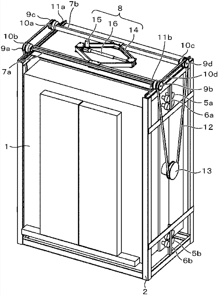
[0059] image 3 is a perspective view of an elevator car. The elevator car consists of an inner car 1 and an outer frame 2 . On the upper part of the inner car 1, a motor for opening and closing the elevator doors (not shown) is installed at a position where it will not interfere with the floor height adjustment mechanism, and controls the power supply control, floor display, and door opening and closing control in the car. Disk 4. The inner car 1 has inner car guide rollers 5a, 5b at the upper and lower portions of the left and right side surfaces. Inner car guide rails 6 are provided on the upper and lower portions of the left and right sides of the outer frame 2 . The inner car 1 is installed in the outer frame 2 so that the inner car guide rail 6 can guide the inner car guide rollers 5a, 5b in the lifting direction.

[0060] The upper part of the outer frame 2 is provided with a floor height adjustment mechanism. The floor height adjustment mechanism is made of crossb...

no. 3 example

[0071] Figure 5 It is a perspective view showing a multi-car elevator in which six elevator cars 18a to 20a and 18b to 20b circulate in the hoistway 17 . The elevator cars 18a to 20a are elevator cars with a floor height adjustment mechanism described in the first embodiment. It is also possible to use a non-illustrated elevator car with a floor height adjustment mechanism according to the second embodiment.

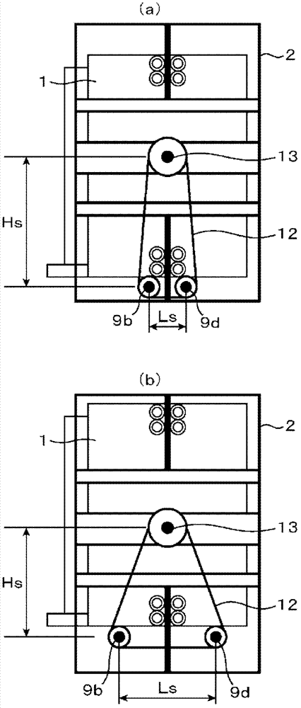
[0072] The floor height adjustment stroke of the floor height adjustment mechanism is set above the maximum deviation of the elevator car from the floor of the destination floor. A pair of elevator cars 18a, 18b are connected in a bucket shape by main ropes 21, 22, and are positioned so that when one of the elevator cars 18a reaches the uppermost floor, the other elevator car 18b reaches the lowermost floor. The main ropes 21, 22 are provided at the front and back of the elevator car 18a, and the elevator car 18a is fixed by two main rope fixing portions 23a, 24a inst...


PUM


Abstract

The invention provides an elevator with a floor height adjusting mechanism, which can not only restrain the height of the elevator car but also slightly adjust the height of the elevator car floor and the height of the floor on the elevator entry without using a hoist. The elevator with the floor height adjusting mechanism comprises an elevating body elevating inside an elevating channel, a main sling hanging the elevating body and a hoist for driving the main sling hung thereon. The elevating body comprises an external frame hung by the main sling, an internal car elevating inside the external frame, auxiliary slings (12) equipped in a ring-shaped way and applied for hanging the internal car on the external frame, more than one hanging spots (13) for hanging the auxiliary sling, more than two movable hanging spots (9a, 9c and 9b, 9d) capable of moving along the horizontal direction and applied for hanging the auxiliary slings; and a switching device for changing the horizontal distance between the more than two movable hanging spots.

Description

technical field [0001] The present invention relates to an elevator that drives two or more elevator car (Car) car rooms in the same hoistway (Shaft), and can adjust the distance between the car rooms. Background technique [0002] As a prior art, there is known an elevator in which two or more elevator cars are driven by a rope wound around a hoisting machine (for example, refer to Patent Document 1). In the above-mentioned elevator, it is impossible to prevent the level difference between the floor of all the elevator cars and the floor of the destination floor only by controlling the hoisting machine. The reasons for the height difference include elongation of the main rope due to long-term use, expansion and contraction of the main rope due to the load of the elevator car, and changes in the passenger load of the main rope due to passengers getting on and off the elevator. And stretching and so on. [0003] Therefore, in the prior art, a zoom structure, an electric win...

Claims


Application Information

Patent Timeline
Patent Type & Authority Patents(China)
IPC IPC(8): B66B1/42
Inventor 清水自由理萩原高行早野富夫
Owner HITACHI LTD
Why Eureka
Try Eureka