
Variable pitch pin row

A technology of variable pitch and pin row, which is applied in the direction of slitting machinery, earthwork drilling and mining, etc., can solve the problems of increasing the vertical component force of the traveling wheel, breaking the end of the vertical plate of the pin row, equipment failure, etc., and reducing the vertical component force , increase the horizontal component force, and improve the effect of meshing characteristics

Active Publication Date: 2015-09-16
NINGXIA TIANDI BENNIU IND GRP +2
View PDF4 Cites 0 Cited by
  • Summary
  • Abstract
  • Description
  • Claims
  • Application Information

AI Technical Summary

Problems solved by technology

[0003] 1. Poor bearing capacity - the main reason is that within the set pin row length, the corresponding pitch is small, so the bearing cross-section of the pin teeth is small, and the strength of this structure is difficult to adapt to the ultra-high-power shearer The need to increase the rated traction force;
[0004] 2. When the trough in the middle of the conveyor bends upward vertically, in the existing structure, the distance between the pin teeth at the ends of two adjacent pin rows (such as Figure 5 P value shown in ), which is larger than the pitch (147 mm) set for each pin row above, and thus will increase the pressure angle when this place meshes with the coal mining machine traveling wheel teeth, and increase The vertical component force on the traveling wheel reduces the horizontal effective traction force, the meshing characteristics between the traveling wheel and the pin teeth deteriorate, and at the same time increases the traction speed fluctuation and impact of the shearer, which brings great negative effects to the smooth operation of related equipment In addition, it is easy to break the end of the vertical plate of the pin row, resulting in serious equipment failure

Method used


Image

  • Variable pitch pin row
  • Variable pitch pin row
  • Variable pitch pin row

Examples


Embodiment Construction

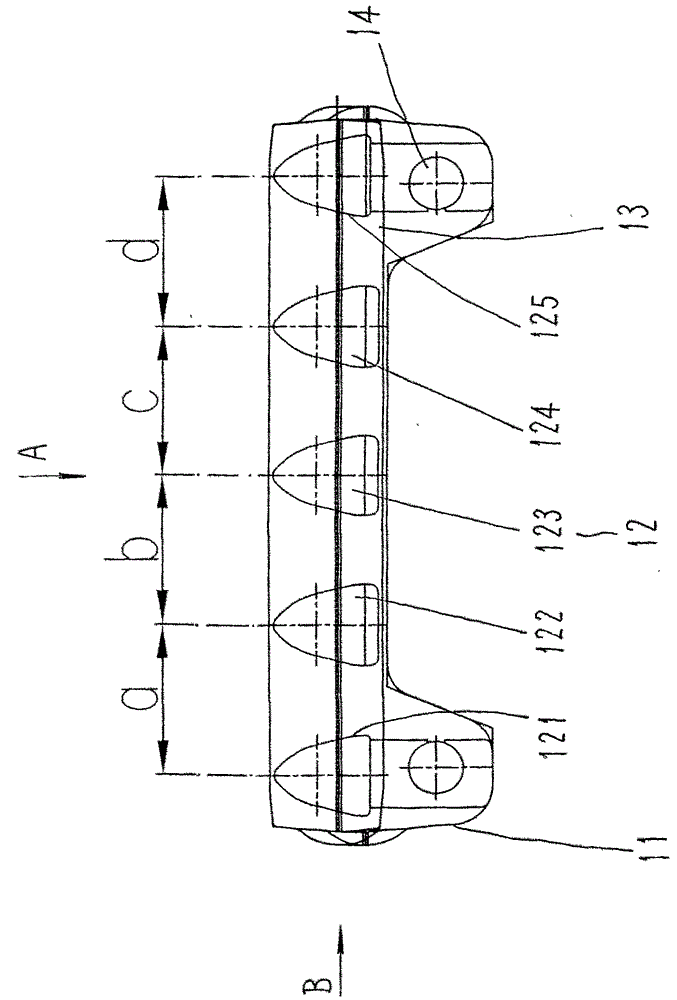
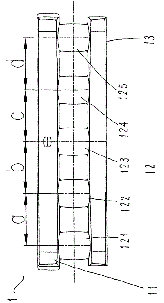
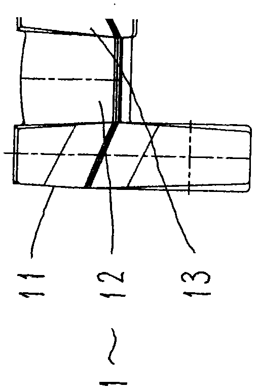
[0015] refer to figure 1 , 2 , 3. The pin row 1 of the variable pitch pin row includes a left vertical plate 11, a pin tooth 12 and a right vertical plate 13, and its basic structure is similar to the existing structure. The left and right vertical plates 11, 13 and the pin teeth are integrally formed. in:

[0016] The pin tooth 12 has the same tooth profile as that of the shearer traveling wheel tooth profile. In the present invention, the number of pin teeth 12 of each pin row 1 is 5, figure 1 , 2 The pin tooth 12 has a first pin tooth 121, a second pin tooth 122, a third pin tooth 123, a fourth pin tooth 124 and a fifth pin tooth 125;

[0017] The distance between the centerlines of two adjacent pin teeth 12 tooth profiles is the pitch of the pin row 1 pin teeth 12, such as figure 1 , 2 As shown, the pitches are expressed as the first pitch a, the second pitch b, the third pitch c, and the fourth pitch d, that is, each pin row 1 has 4 pitches, which is called 4 pitc...


PUM


Abstract

A pin rail with variable pitches mainly solves the technical problem of improvement of meshing properties between pin teeth on a pin rail and wheel teeth of a road wheel of a coal cutter. The technical scheme is that the pin rail with variable pitches comprises a left vertical plate, pin teeth, and a right vertical plate; the left vertical plate is provided with a pin shaft hole for a pin shaft to pass through; the profile of the pin teeth corresponds to the tooth profile of the wheel teeth of the coal cutter road wheel. The invention is characterized in that the pitches at the two ends of the pin rail pin teeth are same; the pitches in the middle of the pin rail pin teeth are same; the pitches at the two ends are larger than the pitches in the middle; the invention is applicable to the meshing transmission of various types of coal cutter road wheels and conveyer pin rails.

Description

Technical field: [0001] The invention relates to an assembly of a conveyor of an underground coal mining face in a coal mine, in particular to a pin row of the conveyor. Background technique: [0002] The coal mining machine in the underground coal mining face of the coal mine is usually finally driven by the meshing transmission of the traveling gear of the coal mining machine and the pin teeth of the pin row series of the conveyor. The pin row series of the conveyor is composed of It consists of multiple pin rows with the same structure. The transmission structure of each pin row fixed on the scraper conveyor includes a pin row, a slot in the middle of the conveyor, a pin row seat and a pin shaft, and a pin is provided on the vertical plate of each pin row. There are also pin holes on the pin row seat, and pin shafts are pierced in the above two pin shaft holes, so that each pin row is connected and installed in the middle groove of the conveyor to form the transmission st...

Claims


Application Information

Patent Timeline
Patent Type & Authority Patents(China)
IPC IPC(8): E21C35/20
Inventor 陈保宗周常飞肖宝贵王振乾陈云贠瑞光吴立忠葛红兵张林王继国
Owner NINGXIA TIANDI BENNIU IND GRP
Learn More