Optical touch panel and light guiding module thereof

A light guide module and optical touch technology, applied in optics, light guides, optical components, etc., can solve the problems of large brightness output and current output, reduce brightness output and current input, save assembly time, and save alignment The effect of the process

Inactive Publication Date: 2012-08-22
PIXART IMAGING INC
View PDF3 Cites 4 Cited by
  • Summary
  • Abstract
  • Description
  • Claims
  • Application Information

AI Technical Summary

Problems solved by technology

[0006] In view of the above problems, the purpose of the present invention is to provide an optical touch panel and its light guide module, so as to solve the problems existing in the prior art that require large brightness output and current output and require repeated and precise alignment during assembly. And other issues

Method used


Image

  • Optical touch panel and light guiding module thereof
  • Optical touch panel and light guiding module thereof
  • Optical touch panel and light guiding module thereof

Examples


Embodiment Construction

[0043] According to the optical touch panel and the light guide module thereof disclosed in the present invention, the light-emitting elements referred to are zero elements installed in the optical touch panel, and the light-emitting elements referred to include, but are not limited to, direct light emitting diodes, Lateral type light-emitting diodes or cold cathode fluorescent lamps (CCFL), and in the following specific embodiments of the present invention, direct light-emitting diodes will be used as embodiments of the present invention.

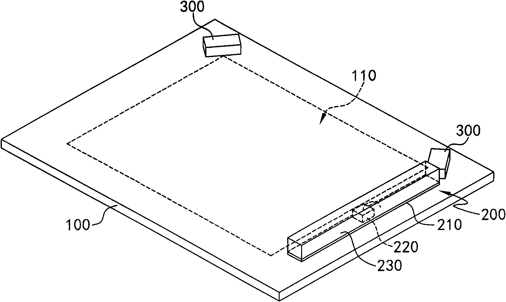
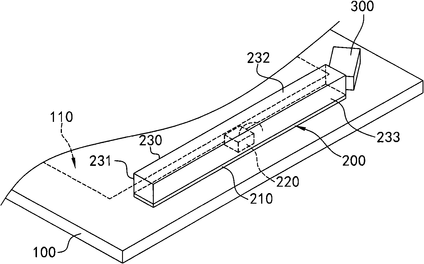
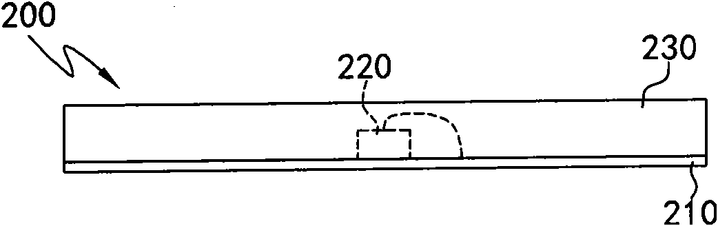
[0044] Figure 1A Is a three-dimensional schematic diagram according to the first embodiment of the present invention, Figure 1B for Figure 1A The enlarged schematic diagram of the light guide module, Figure 1C for Figure 1A Schematic plan view of the light guide module.

[0045] See Figure 1A As shown, the optical touch panel disclosed according to the present invention includes a panel 100, a sensing element 300, and a light guide module 200....


PUM


Abstract

The invention discloses an optical touch panel and a light guiding module thereof. The optical touch panel comprises a panel and a light guiding module, wherein the light guiding module is arranged on the panel, the light guiding module comprises a circuit board, at least one light-emitting component and a light guiding strip, the light-emitting component is electrically arranged on the circuit board, and the light guiding strip is arranged on the circuit board and covers light-emitting component. In addition, light is emitted by the light-emitting component, and the light passes through the light guiding strip and is shot to the panel.

Description

Technical field [0001] The invention relates to an optical touch panel, in particular to an optical touch panel with a light guide module. Background technique [0002] In recent years, the input method of touching the screen with an object or a finger has begun to replace the previous input method of pressing a mechanical button. When the user touches the graphics on the screen, the tactile feedback system on the screen converts the detected light data into electronic signals and transmits them to a processor, and the processor drives various electronic devices with pre-programmed programs. And show vivid audio-visual effects through the screen. [0003] The existing tactile feedback system includes a glass substrate, a light emitting diode (LED), a photosensitive element, a lens, a reflective element, and a light guide element. The photosensitive element, the light emitting diode and the lens are arranged on the upper right corner of the glass substrate, and the reflector and t...

Claims


Application Information

Patent Timeline
IPC IPC(8): G06F3/042G02B6/00F21V8/00F21Y101/02F21Y115/10
Inventor 赖鸿庆李国雄陈晖暄
Owner PIXART IMAGING INC
Why Eureka
Try Eureka